6
STEEkW ed 01/06 EOLO Extra kW
Technical DocumentationTechnical Documentation
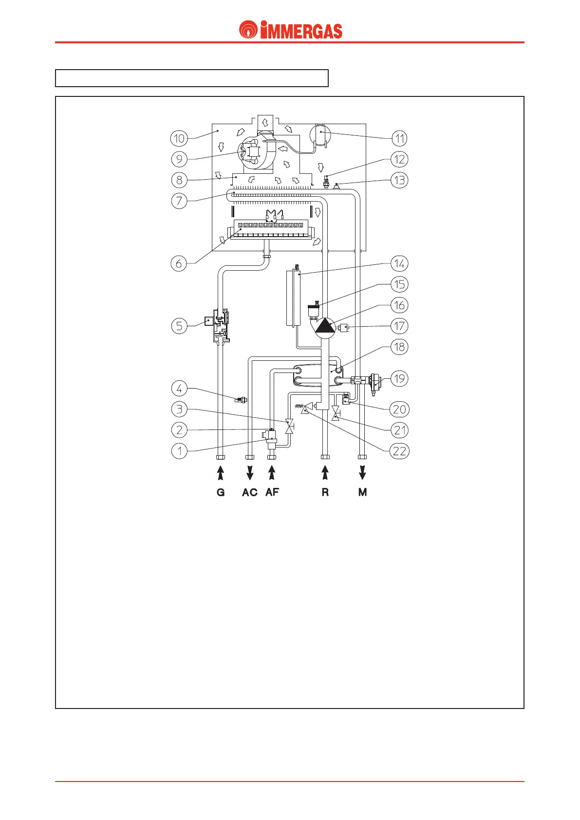
EOLO Extra kW hydraulic diagram.
Legend:
1 - D.h.w. flow switch
2 - Flow limiter
3 - System filling valve
4 - Domestic water probe
5 - Gas valve
6 - Burner
7 - Primary exchanger
8 - Draught diverter
9 - Fan
10 - Airtight chamber
11 - Flue pressure switch
12 - Delivery probe
13 - Safety thermostat
14 - System expansion vessel
15 - Automatic air vent
16 - Boiler circulator
17 - System pressure switch
18 - D.h.w. exchanger
19 - 3-way valve
20 - Automatic by-pass
21 - System draining cock
22 - 3-bar safety valve
G - Gas supply
AC - D.h.w. outlet
AF - D.h.w. (cold) inlet
R - System return
M - System delivery
Hot water for central heating and domestic use is produced
by a primary and secondary (d.h.w.) circuit that are engaged
according to requirements.