7
STEEkW ed 01/06 EOLO Extra kW
Technical Documentation
Technical Documentation
Primary circuit (boiler circuit).
e primary circuit with relevant control and safety devices
is triggered each time there is a request for central heating
or domestic hot water.
Operation.
e heat contained in the flue produced by combustion is ab-
sorbed by the copper blades of the primary water-gas exchanger
(7) which, in turn, transfers it to the water circulating inside
it by means of the boiler pump (16).
e water is transferred directly into the system or else can
be diverted inside the stainless steel instantaneous plate ex-
changer (18).
is depends on the position of the motorised 3-way valve
(19) which, when idle, lets the water flow through the d.h.w.
exchanger (18); on the other hand, when responding to a heat-
ing request, the flow is diverted to the system delivery (M) and
return (R) pipes.
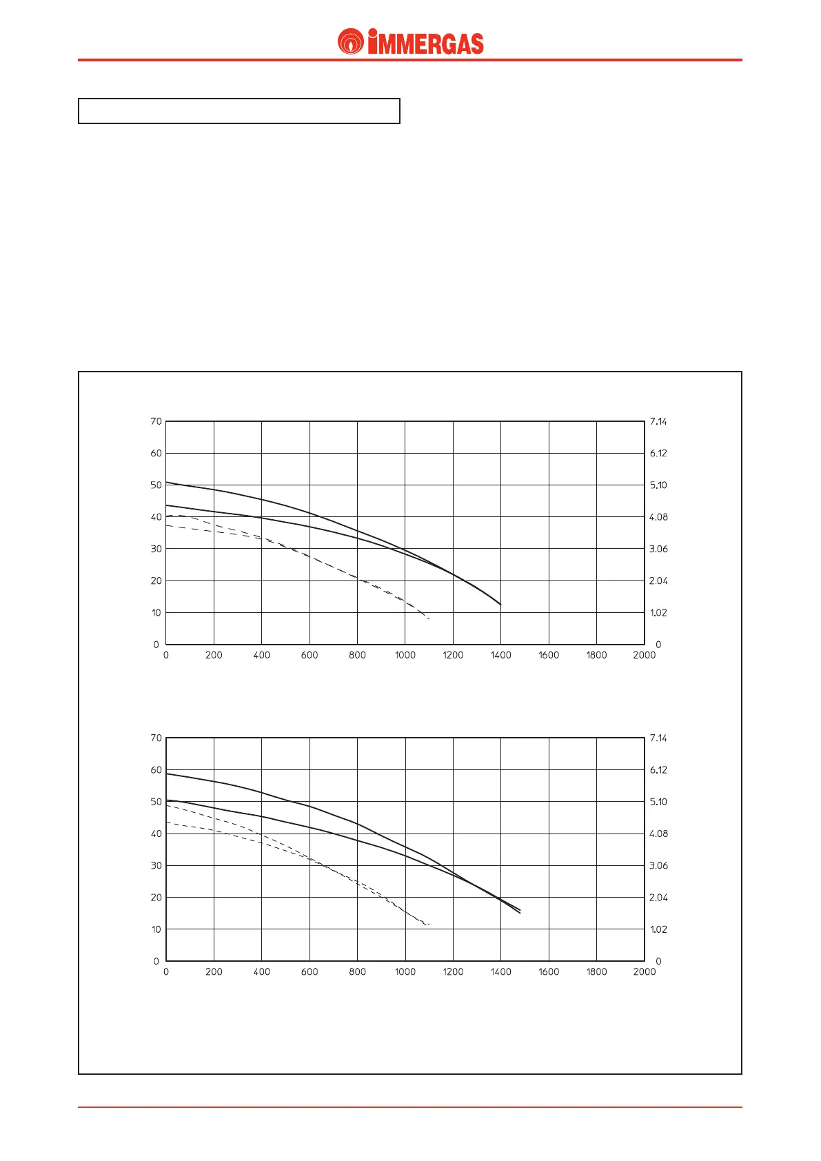
Flow-head graph.
e trend of the curve that represents the system’s flow-head
ratio depends on how fast the pump is working and on how
the system by-pass is adjusted. Depending on the position, it
provides the system with a higher or a smaller head. e cha-
racteristic curves are shown in the following graphs.
D
Flow-rate l/h
A
Head (m H
2
O)
EOLO Extra 24 kW
Head (kPa)
Flow-rate l/h
Head (m H
2
O)
EOLO Extra 28 kW
B
C
A
B
C
D
Head (kPa)
A = Head available to the system on maximum speed with the by-pass off.
B = Head available to the system on maximum speed with the by-pass on.
C = Head available to the system at second speed with the by-pass off.
D = Head available to the system at second speed with the by-pass on.
 Loading...


