28
2-1
CANCEL
LOCK
SET TEMPERATURE(°C)
AUTO
COOL
DRY
HEAT
FAN
HIGH
MED
LOW
TEMP
MODE
SWING TIMER
RESET
ON/OFF
FAN
SPEED
VENT
ECONOMIC
RUNNING
1
2
3
4
5
6
7
8
9
3
13 14
15
10
12
11
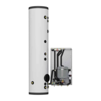
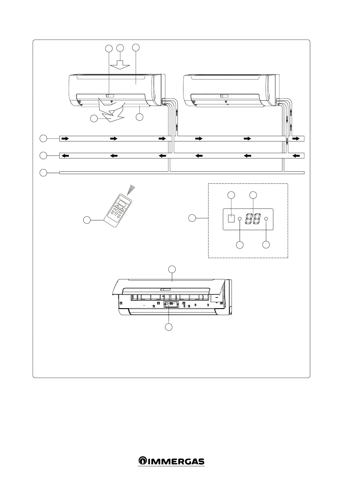
2.4 COMPONENTS.
Key:
1 - Air inlet
2 - Front panel
3 - Display
4 - Air outlet
5 - Horizontal ns
Open the front panel to see the temporary but-
ton for the display panel (12 Fig. 2-1).
is function is used to temporarily start the
unit if the remote control is not positioned cor-
rectly or if the batteries are at.
Two modes can be selected with the “TEMPO-
RARY” button: “AUTO” and “FORCED COOL”.
When the button is pressed, the fan coil will
run in the following order: AUTO, FORCED
COOL, OFF and then AUTO again.
• AUTO
e OPERATION LED is on and the fan coil
runs in AUTO mode. The remote control
works based according to the signal received.
• FORCED COOL
e OPERATION LED ashes, the fan coil
switches to AUTO mode aer forced cooling
with a HIGH fan speed for 30 minutes. e
remote control is not active.
• OFF
e OPERATION LED turns o. e fan coil
is OFF, while the remote control is reactivated.
Note: for the remote control instructions, see
chapter 4.1 “Remote control”.
6 - Remote control
7 - Water inlet pipe
8 - Water return pipe
9 - Drain pipe
10 - Timer indicator
11 - Front panel
12 - “Temporary” button
13 - Infrared signals receiver
14 - Temperature display
15 - Operation LED
 Loading...