29
3-2
3-4
3-5
1 2
3 4
3-1
462
57
290
915
712
1
2
3-3
3-6
1
2
3
4
.
.
.
.
.
.
.
.
.
.
.
.
.
.
.
.
.
.
.
.
.
.
.
.
.
.
.
.
.
.
.
.
.
.
.
.
.
.
.
.
.
.
.
.
.
.
.
.
.
.
.
.
.
.
.
.
.
.
.
.
.
.
.
.
.
.
.
.
.
.
.
.
.
.
.
.
.
.
.
.
.
.
.
.
.
.
.
.
.
.
.
.
.
.
.
.
.
.
.
.
.
.
.
.
.
.
.
.
.
.
.
.
.
.
.
.
.
.
.
.
.
.
.
.
.
.
.
.
.
.
.
.
.
.
.
.
.
.
.
.
.
.
.
.
.
.
.
.
.
.
.
.
.
.
.
34
5
6
1
2
1
2
1
2
3
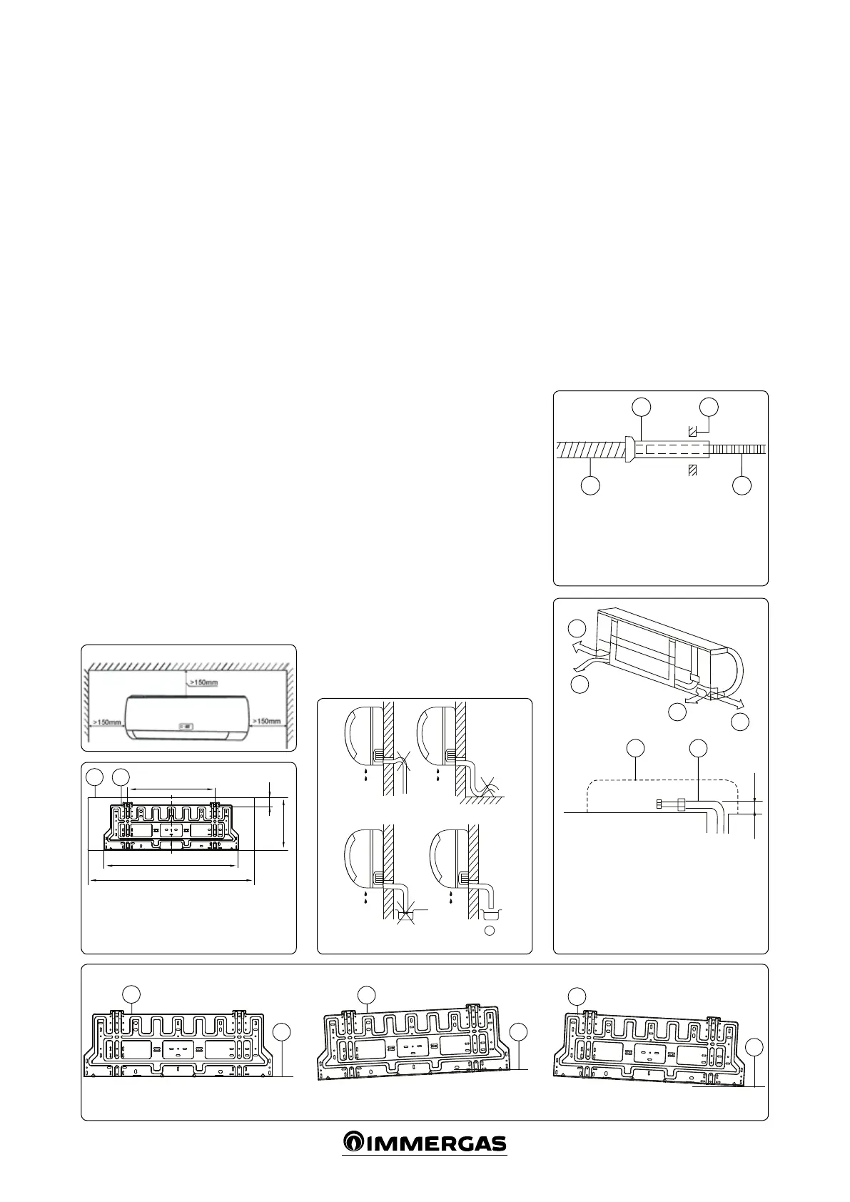
INSTALLATION
3.1 INSTALLING THE INDOOR UNIT.
PLACE OF INSTALLATION.
Installation in the places listed below could be
problematic. If this is unavoidable, call your
local dealer.
• Environments with large quantities of ma-
chine oil.
• Salty environments, such as coasts.
• Environments with high amounts of sulphur
gases, such as spa areas.
• Environments with high frequency machin-
ery, such as wireless equipment, welding ma-
chines and medical facilities.
• Environments that do not contain oxidising
gases and volatile matter.
• Environments with particular environmental
conditions.
• Environments with no obstacles near the en-
trance and exit areas.
• Environments able to contain the indoor
unit.
• Environments suitable for maintenance.
• Environments that have the space indicated
in the diagram around the indoor unit.
• Environments with strong electromagnetic
waves.
• Environments far away from sources of heat,
steam and ammable gasses.
DRILLING THE WALL AND MOUNTING
THE INSTALLATION PANEL.
Installation panel and right way up (unit: mm)
(Fig. 3-1 and 3-2).
• Fixing the installation panel (Fig. 3-3)
- Install the panel horizontally on the struc-
tural parts of the wall using the spacers
around the plate.
- If the wall is in brick, concrete or similar,
drill 5 mm diameter holes. Insert clips for
the mounting screws.
- Fix the installation panel on the wall.
• Drilling the wall
- Determine the position of the pipe hole
using the installation panel and drill a hole
(N95 mm) so that the pipe slopes slightly
downwards.
- Use a special guide for drilling metal rods,
laminated wood or metal plates.
INSTALLING THE CONNECTION AND
DRAIN PIPE
• Drainage
- Insert the drain pipe so that it slopes slightly
downwards. Do not install the drain pipe as
shown in the gure (Fig. 3-4).
- When connecting the drain pipe, insulate
the part connecting the extension with a
shielded pipe (Fig. 3-5).
Do not bend the pipe
Do not insert the end
into the water pipe
• Connection pipe (Fig. 3-6)
- Install the le and rear le pipes as shown
below. Bend the connection pipe to a height
of 43 mm or less from the wall.
- Secure the end of the connection pipe (see
the tightening procedure in the section
on INSTALLING THE WATER PIPES).
When connected, cover all of the pipes
with heat-resistant material.
Note: bend and position the pipe carefully.
Ensure the pipe does not protrude from the
back of the indoor unit.
Make sure the drain pipe is not loose.
Insulate both auxiliary pipes.
Pass the drain pipe under the auxiliary one.
Incorrect installation
Key:
1 - Indoor unit installation panel
2 - Indoor unit gure
Key:
1 - Indoor unit installation panel
Correct installation Incorrect installation
Key:
1 - Shielded pipe
2 - Wall
3 - Drain pipe
4 - Drain pipe extension
Key:
1 - Le pipe
2 - Rear le pipe
3 - Rearright pipe
4 - Right pipe
5 - Indoor unit prole
6 - Connection pipe
2 - Horizontal line
 Loading...