30
3-7
.
.
.
.
.
.
.
.
.
.
.
.
.
.
.
.
.
.
.
.
.
.
.
.
.
.
.
.
.
.
.
.
.
.
.
.
.
.
.
.
.
.
.
. .
.
6
5
4 3
2
1
3-8
3-9
3-10
3-11
3-12
1 2
3
1
2
2
1
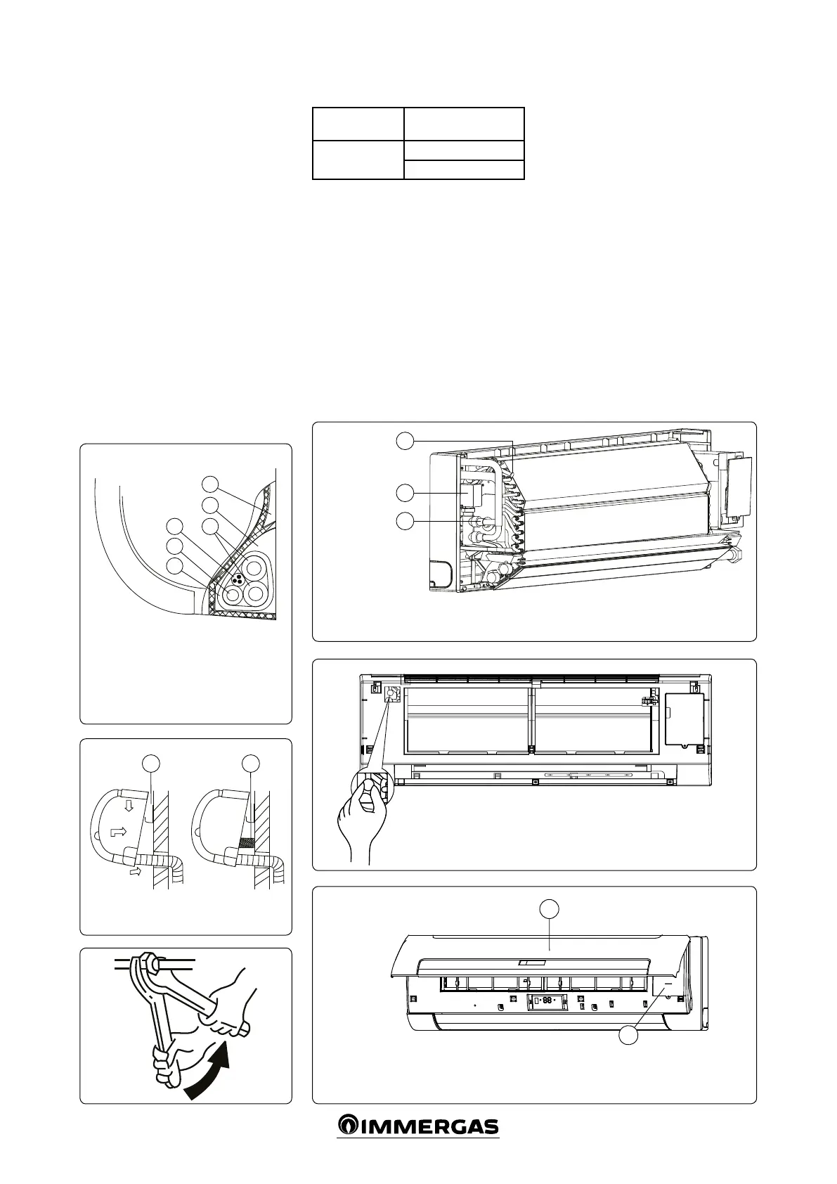
• Connecting the pipes and binding them
(Fig. 3-7)
Wrap the connection cable, the drain pipe
and wires securely and evenly with tape, as
shown below.
- e condensed water generated at the back
of the indoor unit is collected in a special
tank and conveyed outside the room. Do
not put anything else in the tank.
INSTALLING THE INDOOR UNIT (Fig. 3-8)
- Push the pipe through the hole in the wall.
- Place the clamp on the back of the indoor
unit, on the installation panel hook, move
the indoor unit sideways and make sure it is
safely attached.
- e pipes can quickly and easily be connect-
ed by liing the indoor unit with cushioning
material placed between the unit and wall.
Remove when the pipes have been connect-
ed.
- Push the bottom of the indoor unit upwards
along the wall, then move the unit sideways
and downwards to ensure it safely attached.
Indoor unit
3.2 INSTALLING THE WATER PIPES.
PIPES SIZING AND MATERIALS.
Pipe material
Copper pipe for
fan coil
Coil connections
(at plate)
3/4”
3/4”
CONNECTING THE WATER PIPE
e water pipe must be connected by expert tech-
nicians using two spanners for tightening the pipes
of the indoor unit (Fig. 3-9).
Note: Read the installation instructions for
connecting the water pipes of the fan coil with
built-in acceleration device (Fig. 3-10).
- When connected for the rst time, com-
pletely expel the air from the coils through
the outlet valve (g. 3-11).
3.3 WIRING DIAGRAM
Note: e appropriate function is indicated in
the dotted part (can be selected by the user if
required).
Pursuant to applicable national regulations,
xed wiring must have an integrated single-pole
disconnect device with a distance between con-
tacts of at least 3 mm on all poles and a residual
current device (RCD) of at least 10 mA.
e device must be installed in compliance with
the national regulations in force.
- remove the front protection and take o the
plate (Fig. 3-12).
- Connect the power cable and the signal line,
then congure if necessary (Fig. 3-13).
Key:
1 - Collection tank
2 - Space for pipes
3 - Connection pipe
4 - Connection pipe
5 - Drain pipe
6 - Wrapping tape
Key:
1 - Coupling plate
2 - Cushioning material
Key:
1 - ree-way valve (4 ports)
2 - Discharge valve
3 - Connector
Key:
1 - Front panel
2 - Display cover plate