31
3-13
3-14
L N
1 2X Y
E
XT3
RD
BK
G/Y
WH
BL
BK
RD
RD
1 2
12 3
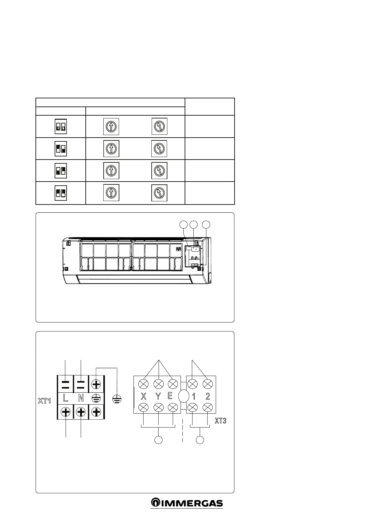
TERMINAL BLOCK DIAGRAM
For wiring, refer to the wiring diagram for the
indoor unit.
- Single-phase indoor unit.
e power cable must be H05RN-F or higher.
Use the shielded twisted pair and connect the
shielding to terminal E (Fig. 3-14).
Indoor unit supply voltage 220-240V~50Hz
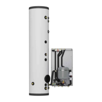
SETTING THE NETWORK ADDRESSES
Every fan coil in the network has only one net-
work address that distinguishes it from all of
the others. e address code for a fan coil in
the LAN is dened by the code switch on the
network interface module (NIM) ranging from
0 to 63.
Toggle switch settings
Network address
code
SW1 ENC2
~
2
6
7
A
B
C
D
E
1
2
3
4
5
6
7
A
E
F
00÷15
ON
2
~
2
3
4
5
6
7
A
E
2
6
7
A
B
C
D
E
16÷31
ON
1
2
~
2
3
4
5
6
7
A
E
2
6
7
A
B
C
D
E
32÷47
ON
1
2
2
3
4
5
6
7
9
A
E
2
6
7
A
B
C
D
E
48÷63
Key:
1 - Signal line cable tray (5 positions)
2 - Power cable cable tray (3 positions)
3 - Conguration dip switch
Key:
1 - to the BUS COMM. central con-
trol monitor (CCM)
2 - ON/OFF control from hydronic kit
Colour code key:
BK - Black
BL - Blue
G / Y - Yellow / Green
RD - Red
WH - White
 Loading...