32
3-15
CANCEL
LOCK
SET TEMPERATURE(°C)
AUTO
COOL
DRY
HEAT
FAN
HIGH
MED
LOW
TEMP
MODE
SWING TIMER
RESET
ON/OFF
FAN
SPEED
VENT
ECONOMIC
RUNNING
1
2
3
3-16
AD ALETTE
BRANDEGGIANTI
L
N
M
M
DISPLAY
Y
(E)
X
QUADRO DI COMANDO
AL MONITOR
DI CONTROLLO CENTRALE
A INTERRUTTORE ON/OFF
VALVOLA
CN6
CN3
CN23
CN1
CN19
CN9
CN5
CN21
CN10
CN8
CN14
MOTORE
INT1
ENC2
Y/G
RD
WH
BL
BK
BK
CN301
CN1
CN2
GY
21
MODBUS RTU
N
IMPOST. PREDEFINITA
CN18
TEMP. AMB.SENSORE T1
TEMP. TUBO SENSORE T2
CN24
TERRA
A UNITA’SUPERIORE
S W1
ON
1 2 3 4
CN12
alta tensione
ALLARME
CN15
ON
BR BL
COMANDO ON/OFF
DA KIT IDRONICO
VENTILATORE
BL
Si prega di utilizzare un cavo tripolare schermato
e di collegare la schermatura a terra!
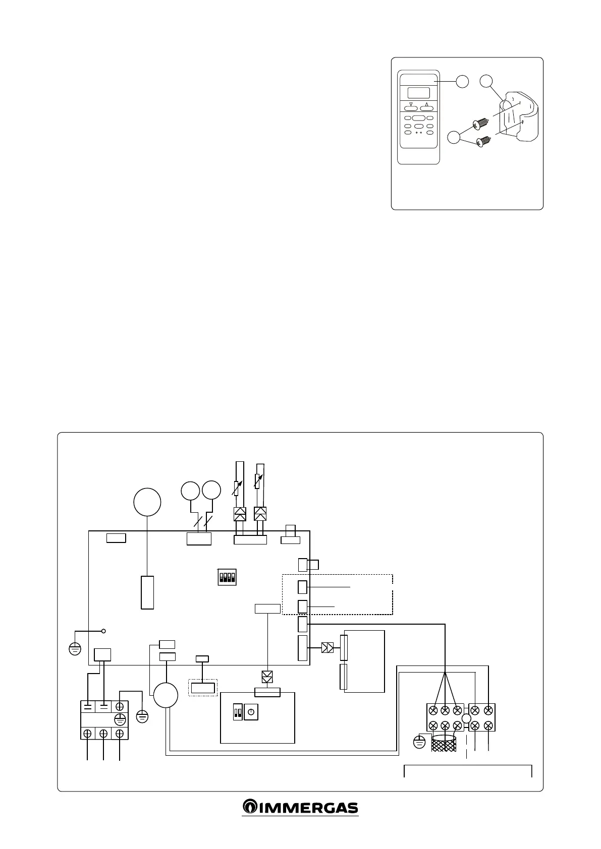
PRECAUTIONS WHEN INSTALLING THE
REMOTE CONTROL (Fig. 3-15)
- Do not throw or hit the remote control.
- Before installation, try the remote control
and check its position is within the reception
range.
- Keep the remote control at least 1 metre
away from the nearest TV or stereo equip-
ment (image or noise interferences should be
avoided).
Colour code key:
BK - Black
BL - Blue
GY - Grey
G / Y - Yellow / Green
RD - Red
WH - White
3.4 FAN COIL WIRING DIAGRAM.
- Do not install the remote control in places
exposed to direct sunlight or near sources of
heat, like the cooker.
- Make sure the positive and negative poles are
positioned correctly when charging the bat-
teries.
- If the product is technically improved, this
manual will be subject to variations without
forewarning.
Key:
1 - Remote control
2 - Mounting screw B ST2.9x10-C-H
3 - Remote control mount
MOTOR WITH
SWINGING
FINS
T1 SENSOR ROOM TEMP.
T2 SENSOR PIPE TEMP.
FAN
MOTOR
MODBUS RTU
TO ON/OFF SWITCH
EARTH
high voltage
VALVE
ALARM
DISPLAY
TO CENTRAL CONTROL
MONITOR
ON/OFF CONTROL
FROM HYDRONIC KIT
Please use a shielded triple cable and earth the shielding!
CONTROL PANEL
PREDEF. SETTING
SUPPLY VOLTAGE
TO THE TOP UNIT