13
C
12
1-13 1-14
1-15
C
12
1-16
C
12
5
4
3
1
2
1
2
3
4
5
6
C
12
INSTALLERUSERMAINTENANCE TECHNICIAN
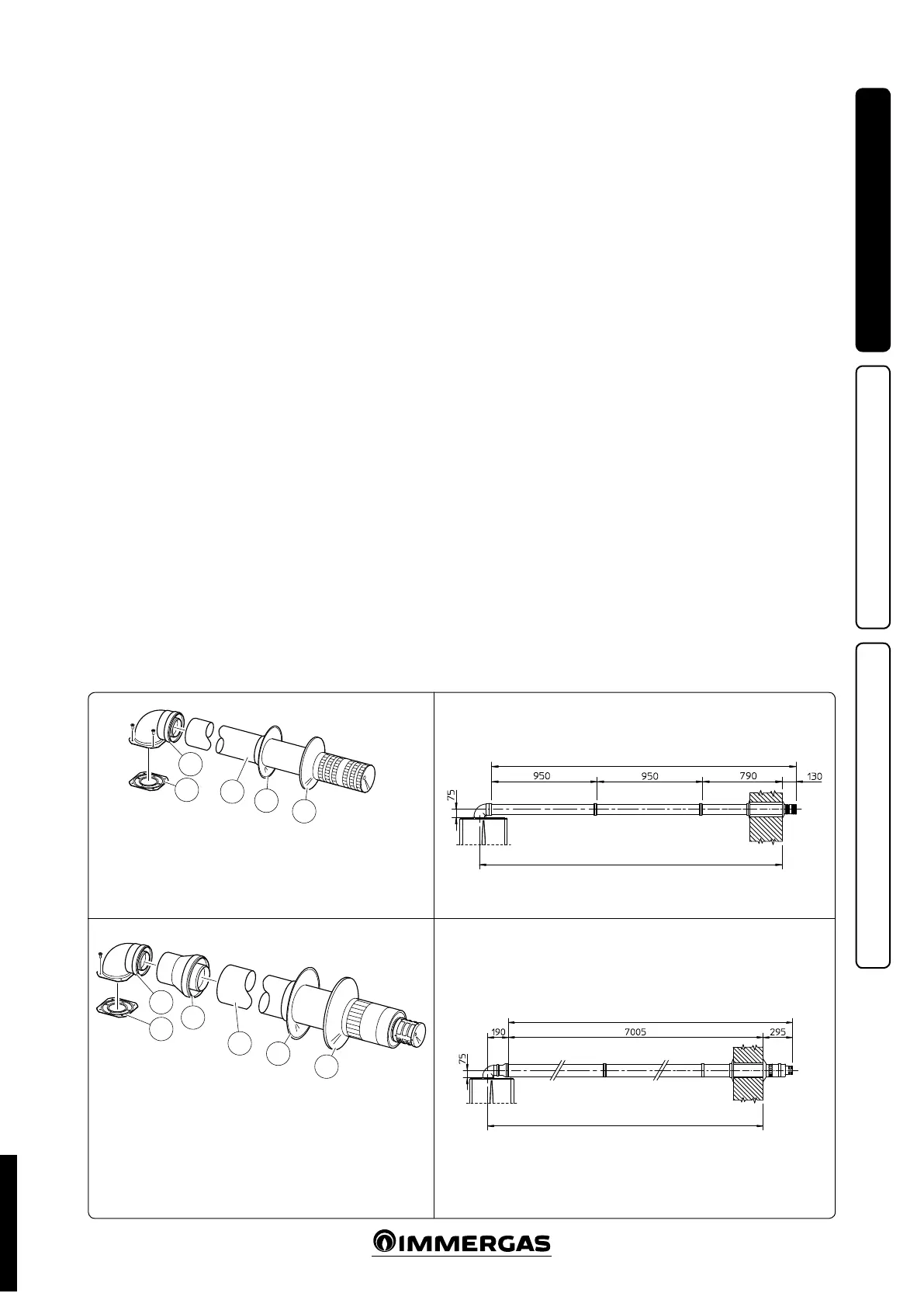
1.11 CONCENTRIC HORIZONTAL KIT
INSTALLATION.
Type C configuration, sealed chamber and
fan assisted.
e position of the terminal (in terms of dis-
tances from openings, overlooking buildings,
floor, etc.) must be in compliance with the
regulations in force.
is terminal is connected directly to the outside
of the building for air intake and ue exhaust. e
horizontal kit can be installed with the rear, right
side, le side or front outlet. For installation with
frontal outlet, one must use the xing plate and
a concentric bend coupling in order to ensure
sucient space to carry out the tests required
by law upon commissioning.
Horizontal intake-exhaust kit Ø 60/100 Kit
assembly (Fig. 1-13): install the bend with ange
(2) onto the central hole of the boiler inserting
the gasket (1) and tighten using the screws in-
cluded in the kit. Couple the terminal pipe (3)
with the male end (smooth) into the female end
of the bend (with lip seals) up to the stop; mak-
ing sure that the internal wall sealing plate and
external wall sealing plate have been tted, this
will ensure sealing and joining of the elements
making up the kit.
• Extensions for Ø 60/100 horizontal kit (Fig.
1-14). e kit with this conguration can be
extended up to a max. 2,82 horizontal m in-
cluding the terminal with grid and excluding
the concentric bend leaving the boiler. is
conguration corresponds to a resistance factor
of 100. In this case the special extensions must
be requested.
NOTE: when the boiler is installed in areas where
very cold temperatures can be reached, a special
anti-freeze kit is available that can be installed as
an alternative to the standard kit.
Horizontal intake-exhaust kit Ø 80/125 Kit
assembly (Fig. 1-22): install the bend with ange
(2) onto the central hole of the boiler inserting
the gasket (1) and tighten using the screws in-
cluded in the kit. Fit the male end (smooth) of
the adapter (3) up to the end stop on the female
side of the bend (2) (with lip seal). Fit the Ø
80/125 (4) concentric terminal pipe with the male
end (smooth) to the female end of the adapter
(3) (with lip gasket) up to the end stop; making
sure that the internal and external wall sealing
plates have been tted; this will ensure sealing
and joining of the elements making up the kit.
Max 2820
Max 2805
Max 7300
Max 7195
e kit includes:
N° 1 - Gasket (1)
N° 1 - Concentric bend Ø 60/100 (2)
N° 1 - Int./exhaust concentric terminal Ø 60/100 (3)
N° 1 - Internal wall sealing plate (4)
N° 1 - External wall sealing plate (5)
e kit includes:
N° 1 - Gasket (1)
N° 1 - Concentric bend Ø 60/100 (2)
N° 1 - Adapter Ø 80/125 (3)
N° 1 - Int./exhaust concentric terminal Ø 80/125 (4)
N° 1 - Internal wall sealing plate (5)
N° 1 - External wall sealing plate (6)
• Extensions for horizontal kit 0 80/125 (Fig.
1-16). e kit with this conguration can be
extended up to a max. horizontal length of
7.3 m including the terminal with grid and
excluding the concentric bend leaving the
boiler and the adapter 0 60/100 in 0 80/125.
is conguration corresponds to a resistance
factor of 100. In this case the special extensions
must be requested.
STD.002998/004