9
STV50 ed 09/08 VICTRIX 50 Rev. 002
Fan.
is operates upstream from the combustion chamber and it is
physically positioned at the bottom of the sealed chamber.
It is controlled by the integrated board with a positive square
wave signal with a variable ON-OFF (duty-cycle) ratio.
Its speed is adjusted (from about 1250 to about 5200 rpm) ac-
cording to the output required and is controlled by means of
a Hall eect sensor which reads the rpm.
e fan extracts the combustion air from the top of the draught
diverter through a plastic pipe (1) that helps reduce noise and
optimises burner ignition.
Variations in the ow of air entering the mixing duct results
in a variation in the pressure (P1) signal at the inlet of the
Venturi pipe and enables the pneumatic valve to regulate
exiting gas pressure.
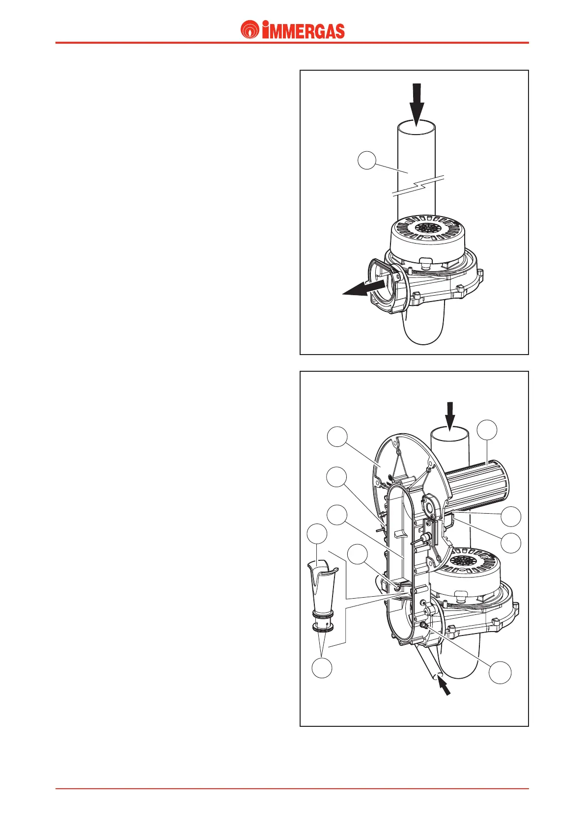
Venturi.
e Venturi pipe (1) is tted in a sealed duct (6) inside which
the combustion air and gas are mixed.
e air is driven to the bottom of the duct by the fan, while
the exiting gas from the valve is injected at the Venturi pipe
(1) inlet by a nozzle (2).
e transit of air in the pipe creates vacuum (“Venturi eect”)
which, through the 4 holes (3) in the base, “drags” the gas
inside and mixes it with the air.
e nozzle (2) diers in diameter according to whether natural
gas or LPG is used; in fact working with both gases at a more or
less constant pressure, its section determines correct gas ow.
At the end of the Venturi pipe is a pressure pick-up point where
the input signal (P1) is read.
is signal is conveyed to the pneumatic valve regulating the
gas pressure via a silicone pipe.
GAS
AIR
Technical Documentation
Technical Documentation