Do you have a question about the Immergas VICTRIX 75 and is the answer not in the manual?
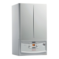
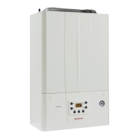
Overview of the VICTRIX 75 boiler's key characteristics and capabilities.
Visual representation of the boiler's external measurements and connection points.
Labeled diagram identifying the key internal parts of the boiler.
Description of the boiler's control panel, including display and keys.
Labeled diagram illustrating the boiler's internal water circulation pathways.
Explanation of the boiler's primary circuit, including heat exchange and pump function.
Graphical representation of the flow rate versus head pressure relationship.
Details on how the boiler's pump operates within the primary circuit.
Description of the condensation module, its elements, and connections.
Explanation of system pressure switch and ISPESL approved safety valve.
Description and function of gas valve, electrical coils, and pneumatic unit.
Explanation of how the fan, Venturi pipe, and burner interact for combustion.
Details on the fan's role in air intake and its speed control.
Explanation of the Venturi pipe's effect on gas and air mixing.
Details on the burner's construction, pre-mixing, and low-flame operation.
Function and placement of ignition and detection electrodes for burner control.
Step-by-step guide for removing gas nozzle, burner, flue hood, and electrodes.
Procedure for adjusting nominal and minimum heat output via fan speed settings.
Guidelines for adjusting the air-gas ratio based on CO2 measurements.
Steps for calibrating minimum CO2 levels using the gas valve adjustment screw.
Instructions for adapting the boiler for different gas types, including nozzle and parameter changes.
Explanation of how the fan expels flue gases and how condensation is managed.
Description of the condensate drain trap and its function in preventing flue gas escape.
Details on the flue hood's role and the location of air-flue intake sampling points.
Explanation of the sealed chamber setup, including air inlet and exhaust mechanisms.
Details on horizontal and vertical concentric kits for air and exhaust connections.
Explanation of the open chamber setup, air inlet, exhaust, and associated kits.
Installation details for the 80 Ø horizontal kit with wall discharge.
Guidance on using flexible ducting for flue exhaust connection.
Installation details for the 80 Ø horizontal kit with flue discharge.
Diagram and explanation of the boiler's main electrical connections and power supply.
Overview of electrical safety devices and their functions.
Details on various electrical components powered by the boiler, including loads and transformers.
Explanation of the low voltage circuit and its components.
Description of sensors and switches that provide input to the boiler's control system.
Explanation of the boiler's output signals controlling various components.
Electrical sequence for central heating operation with thermostat and thermoregulation.
Diagram of the PCB and explanation of its primary functions and display.
Description of how the PCB manages central heating requests via thermostat and thermoregulation.
Explanation of operation for domestic hot water, antifreeze, and chimney sweep functions.
Detailed explanation of various input signals like BUS, switches, and probes.
Description of the function of the MODE, RESET, STEP, and STORE keys.
Explanation of output signals controlling gas valve, ignition, pump, diverter valve, and fan.
Description of BUS output for communication and the display output.
Overview of safety devices like pump antilock, ignition lock, and overtemperature thermostats.
Details on post-circulation and post-ventilation functions for safety.
Safety measures for NTC probe failures and fan operation issues.
Description of the boiler's control panel, display, keys, and operating modes.
Procedure for accessing and modifying boiler operating parameters.
List and description of parameters adjustable by the user without an access code.
Explanation of the INFO mode for viewing values and the step-based parameter access.
Procedure for entering the technician access code to alter reserved parameters.
Table showing parameters adjustable by users without an access code.
Table detailing parameters accessible only by technicians, including limits and factory values.
Permanent error codes (E) and their remedies, requiring manual reset.
Temporary error codes (b) and conditions for automatic boiler re-operation.
Step-by-step process of the boiler's operation during the heating phase.
Table listing key technical specifications like heat output, efficiency, and electrical data.
Table detailing gas nozzle diameters, pressures, and variable heat output data.
General guidance on installing a single VICTRIX 75 boiler and optional kits.
Details on the ISPESL safety kit for compliance with standards.
Information on the kit for connecting an external storage tank for DHW.
Details on the kit for increasing water circulation in large systems.
A schematic example of a single boiler installation with a legend.
A schematic example of a three-boiler cascade installation with a legend.
Details on ISPESL safety kits for cascade installations.
Information on the flue manifold kit for connecting multiple boilers.
Detailed schematic example of a cascade system with component legends.
A comprehensive list of optional accessories and their corresponding product codes.
| Power Output | 75 kW |
|---|---|
| Fuel Type | Natural Gas / LPG |
| Max. Heating Output | 75 kW |
| Protection Rating | IPX5D |
| Type | Condensing |
| Electrical connection | 230 V / 50 Hz |
