25
STV75 ed 01/08 VICTRIX 75
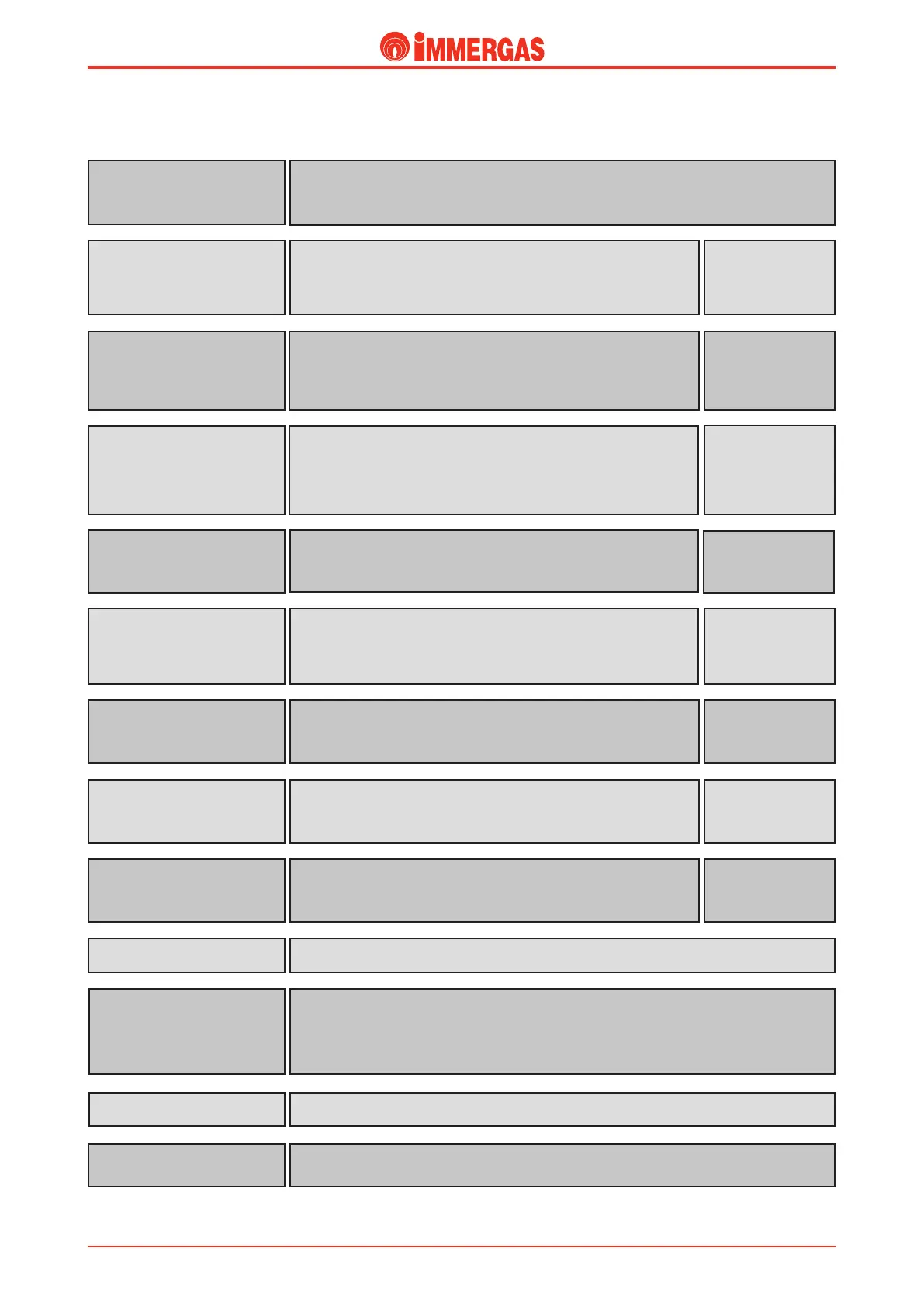
Inputs.
It powers the integrated board and allows operation of the boiler in the
central heating or d.h.w. mode (if the 3-way diverter valve for an external
storage tank kit is installed).
Main switch
(S1)
Open = Power OFF
Closed = Power ON
It is a signal that indicates ame detection.
It lets the integrated board increase fan speed after having limited it during
the ignition phase.
Flame detection
(Ionisation electrode)
(E2)
It is a resistor that varies in an inversely proportionate way to the external
temperature.
It lets the integrated board vary the system ow temperature in accordance
with external temperature.
External probe (B4)
(external optional))
NTC probe
12 kΩ 25 °C
It is a resistor that varies in an inversely proportionate way to the tempera-
ture of the ow water in the primary circuit.
It is used as a limit thermostat on the ow (95°C).
Flow probe
(B1)
NTC probe
12 kΩ 25 °C
It is a resistor that varies in an inversely proportionate way to the tempera-
ture of the return water in the primary circuit.
It is used as a limit thermostat on the return (90°C).
Return probe
(B5)
NTC probe
12 kΩ 25 °C
It is a resistor that varies in an inversely proportionate way to the domestic
hot water temperature.
Domestic hot water probe
(B2)
(external optional)
NTC probe
12 kΩ 25 °C
When the pressure in the primary circuit is below 0.3 bar, it does not en-
able burner ignition, preventing the start of the ignition cycle, error code
“b 26” is displayed on the boiler control panel monitor.
System pressure switch
(S5)
Open =
no pressure
Closed =
pressure OK
By means of this signal the zones and cascade regulator is able to communicate with the boiler’s
integrated board.
BUS input
(external optional)
When closed it enables operation in the domestic hot water mode, disabling
operation in the central heating mode.
Summer switch
(S16)
(not provided to Immergas)
Open = Central
Heating ON
Closed = Central
Heating OFF
To Reset the integrated board subsequent to a malfunction of boiler shutdown signalled with the
relative error code “E....” (see list of error codes and malfunctions).
is is done on the boiler control panel with the RESET push button.
RESET key
To select the menu that appears on the Display.MODE key
To select the parameter to display or modify.
STEP key
To conrm and store the data entered.STORE key
Flame signal =
6 ÷ 15 microA
Technical Documentation
Technical Documentation