15
STV75 ed 01/08 VICTRIX 75
Air inlet and exhaust systems.
(see air inlet and exhaust end pieces nstructions).
VICTRIX 75 boilers are type approved for installation outside
and inside a heating station.
e “VICTRIX 75” boiler leaves the factory with a “B23” type
conguration (fan-assisted open chamber); to change the con-
guration into a “C” type (fan-assisted sealed chamber) you
have to remove the 80 Ø adapter, the bracket and the seal on
the boiler cover so you can then use the specic kits.
For a correct installation of the VICTRIX 75 boiler it is neces-
sary to use the specic set of air inlet and exhaust pipes that
have been designed to be used exclusively with the VICTRIX
75 series of condensation boilers.
“GREEN SERIES” ue pipes for the VICTRIX 75 are made
of plastic (PPS = self-extinguishing polypropylene) suitable for
resisting the corrosive action of acid condensation as they are
specic for this kind of appliance.
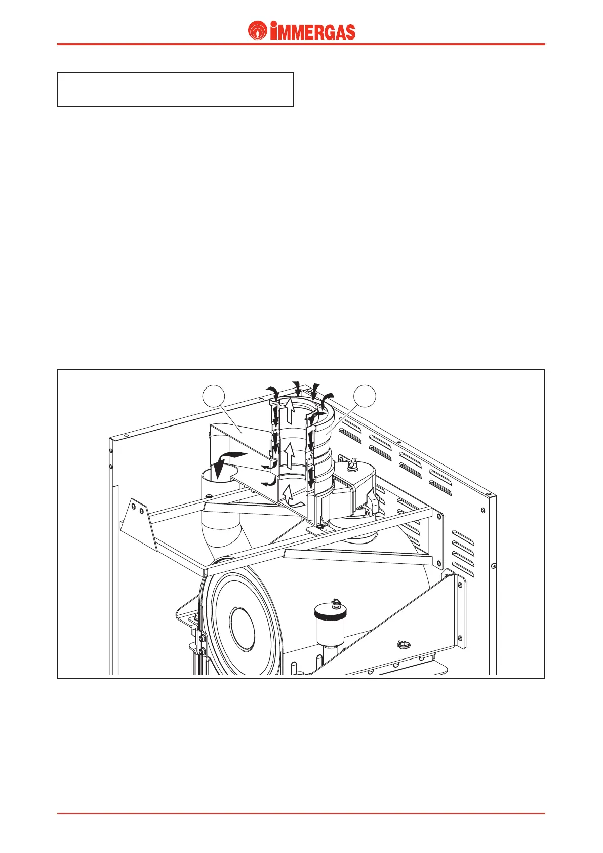
Fan-assisted sealed chamber conguration
(type C).
Air inlet.
e vacuum that is created when the fan is working allows
the inlet of combustion air through the external concentric
hole (125 Ø) of the concentric adapter (2) slotted into the
draught diverter (1) which is connected to the fan with a
plastic pipe.
In this way air inlet occurs outside the room where the boiler
is installed.
Exhaust.
Likewise, the discharge of the products of combustion occurs
by exploiting the narrowest hole (80 Ø) on the draught diverter
(1) which, by means of the concentric adapter (2), is coupled
to the concentric air inlet and exhaust ues.
In this way the ue are expelled outside the room where the
boiler is installed.
Technical Documentation
Technical Documentation