14
STV75 ed 01/08 VICTRIX 75
Condensate drain trap (4).
It takes the condensate from the bottom of the module since
this condensate collects when the boiler is working.
Its outlet is connected to the drain pipe (11) towards which it
allows the passage of water but not ue which could happen
if the evacuation pipes get clogged.
e trap’s water column is, in fact, higher than the pressure
inside the sealed chamber (module) with the fan working at top
speed and the evacuation pipes clogged to working limits, thus
avoiding the products of combustion from being discharged
through the condensate drain. When switched on for the rst
time the ue could be discharged through the drain pipe (11)
but this stops after only a few minutes once the condensate
has reached the appropriate height. If this does not happen
soon, ll the trap with water after rst having removed the
small pipe (10) which must be put back in place when you
have nished.
Air-ue intake traps (8-9).
e top of the appliance features two intake traps with screw
closing accessible from the front (after having removed the
plastic cover) and from where combustion air (8) and ue (9)
can be sampled.
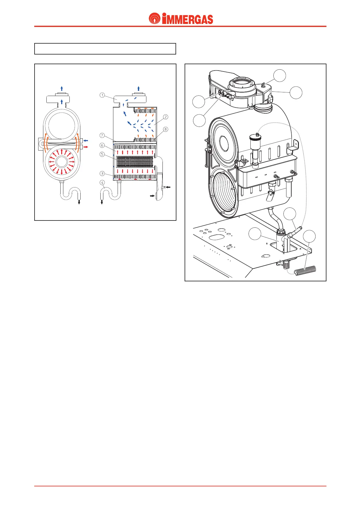
Flue circuit.
Operation.
Operation of the fan positioned at the inlet of the air-gas mix
duct ensures the forced expulsion of the exhaust ue produced
by the cylindrical burner (5).
e ue directly hit the rst eight elements of the primary
exchanger tted in the sealed combustion chamber (6) on
the bottom of which is a steel plate (7) that separates it from
the condensation chamber (2) and deviates the ue outside
the module.
In this way, the exhaust gases, before entering the condensation
chamber (2), hit the last three (3) elements of exchanger inside
which the primary circuit return water ows.
is cools the products of combustion even more and fa-
cilitates condensation before exiting through the draught
diverter (1).
e condensation water that forms inside the exchanger, in
the draught diverter and possibly in the extraction ducts, ows
down to the bottom of the module from where, before being
runo, it is conveyed to a siphon (4).
Flue hood (1).
is is connected to the top of the condensation module and con-
veys the combustion products to the ue exhaust at the top of the
appliance.
It is involved in the transit of the ue and the condensation water
that has formed inside or in the exhaust pipes.
It is made of plastic resistant to the corrosive eects of condensate
and is suitable for working at a temperature of up to 130 °C (max
ue temperature with 85 °C ow = 78 °C).
e ue hood and ue exhaust duct are protected by a thermostat
(12) that is triggered when the temperature exceeds 90 °C.
Gas
Air
Condensate discharge
Flue exhaust
Flue exhaust
M
R
Technical DocumentationTechnical Documentation