7
STV75 ed 01/08 VICTRIX 75
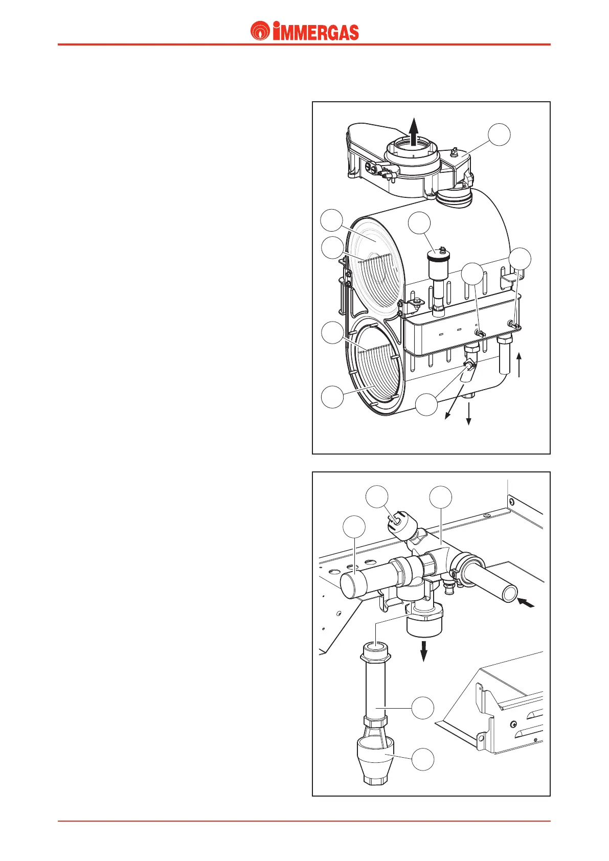
Primary heat exchanger
(condensation module).
It consists of a casing containing 12 coil shaped elements.
Each element is made of 5 elliptic pipe spirals (3).
e whole module is made of stainless steel. e lower sec-
tion is the sealed combustion chamber while the top is the
condensation chamber (4).
e eight lower elements are heated directly by the cylindrical
burner, while the top four are located inside the condensation
chamber (4) which is separated from the combustion chamber
by a metal plate (see the ue circuit).
To minimise head losses and increase the ow available for
the system, the ow consists of the parallel connection of six
elements while the return consists of the parallel connection
of the remaining six elements.
e exchanger inlet is connected to the boiler pump ow on
which the system return NTC probe is positioned (6) while the
outlet, on which the system ow (7) NTC probe is positioned,
is connected to the primary circuit ow.
readed ttings and a at seals are used to couple the ow
and return pipes of the primary circuit.
e overheating safety thermostat (1) is installed on the system
ow pipe.
e ue hood (5) is connected to the top of the module by a
seal and fastened to the supporting frame by screws.
Condensation is runo from the bottom.
Safety devices and controls.
System pressure switch (2).
is switch detects the pressure inside the primary circuit.
It is housed on the ow manifold body and coupled to a
microswitch that prevents the burner working when pressure
is below 0.3 bar.
It prevents the main exchanger from overheating.
ISPESL type approved 4 bar safety valve (3).
It prevents the safety pressure from being exceeded in the
circuit (4 bar).
It is located at the front of the ow manifold body to which
it is coupled.
When this valve trips it causes water to come through the
system ow pipe to which an extension pipe (4) is connected
that ends with a collection funnel (5).
System
ow
Flue
Condensate
discharge
System
return
System
ow
Technical Documentation
Technical Documentation