6
STV75 ed 01/08 VICTRIX 75
Primary circuit (boiler circuit).
e primary circuit with relevant control and safety devices
is triggered each time there is a request for central heating
or antifreeze.
Operation.
e heat contained in the ue produced by combustion is
absorbed by the pipes of the coil water-gas exchanger tted in
the condensation module (13), which, in turn, transfers it to
the water circulating inside thanks to the boiler pump (28).
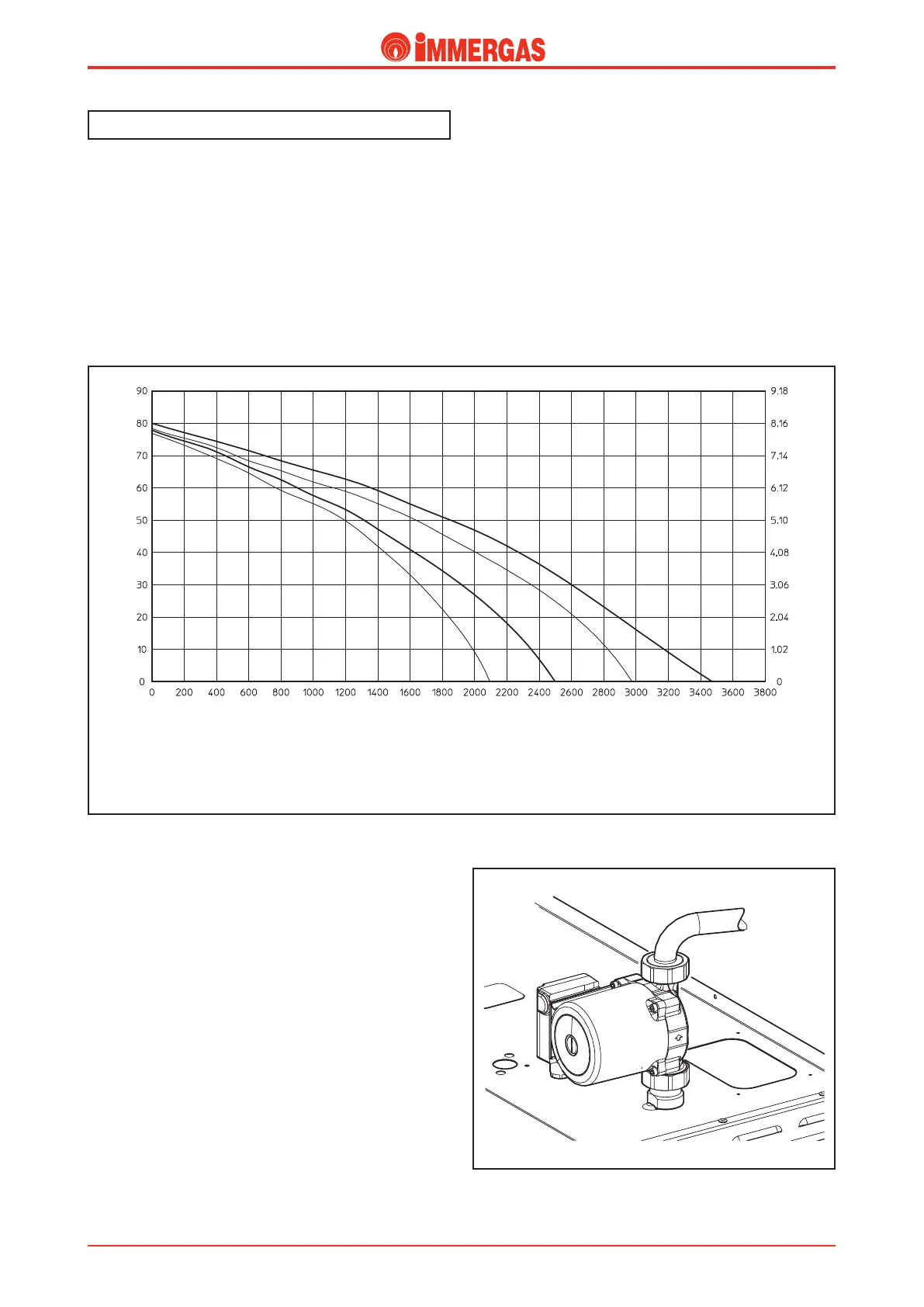
Flow-head graph.
e trend of the curve that represents the ow-head ratio
depends on pump speed.
Flow rate (litres/h)
A
B
C
Head (kPa)
Head (m c.a.)
A = Head available to the system at maximum single boiler speed
B = Head available to the system at second single boiler speed
C = Head available to the system at maximum speed with check valve for boilers in cascade (battery)
D = Head available to the system at second speed with check valve for boilers in cascade (battery)
D
Pump.
e pump works on the primary circuit return and it is physi-
cally coupled to the components supporting plate.
Technical DocumentationTechnical Documentation