13
STV75 ed 01/08 VICTRIX 75
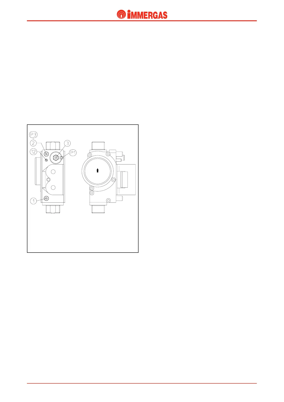
Legend:
1 - Gas valve inlet pressure point
2 - Gas valve outlet pressure point
3 - O/Set adjustment screw
12 - Outlet gas ow regulator
Calibrating minimum CO
2
.
- after calibrating the maximum CO
2
value, switch the boiler
on and run at minimum output by pressing and holding the
"MODE" and "-" buttons simultaneously for two seconds.
is forces the boiler to operate at minimum power and the
letter "L" appears on the screen, followed by a two gure
number indicating the primary circuit temperature;
- take a fume sample, inserting the analyser probe complete-
ly;
- check that the measured carbon dioxide (CO
2
) value is within
the limits specied for minimum power in the table above;
- if the values are incorrect, restore them to the limits by
turning the gas valve’s oset adjustment screw (3).
By turning the screw clockwise the CO
2
value increases while
it decreases by turning the screw counter clockwise.
Gas conversion.
By using the special kits (natural gas or LPG) the appliance
can be adapted to a type of gas dierent to that for which the
boiler is factory set: Conversion involves replacing the gas noz-
zle positioned at the inlet of the Venturi pipe and regulating
the maximum and minimum heat outputs by varying max.
fan rpm in central heating of paramenter “No. 22” and min.
fan rpm in central heating of parameter “No. 26” (see nominal
and minimum heat output adjustment).
Finally, check the carbon dioxide (CO2) value at maximum
and minimum output and if necessary adjust by means of the
o-set signal (see air-gas ratio adjustment).
Technical Documentation
Technical Documentation