41
STV75 ed 01/08 VICTRIX 75
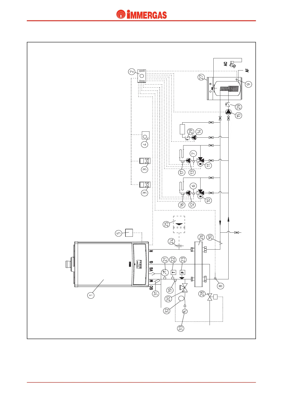
Example of a single VICTRIX 75 installation.
Legend:
1 - VICTRIX 75 generator
2 - Cascade and zone regulator
3 - Zone regulator
4 - Modulating room thermostat
5 - External probe
6 - No.1 zone temperature probe 1 (CMI-1)
7 - No.2 zone temperature probe 2 (CMI-2)
8 - Shared ow probe
9 - Water tank temperature probe
10 - No.1 Zone mixing valve (CMI-1)
11 - No.2 Zone mixing valve (CMI-2)
12 - No.1 Zone central heating circuit pump (CMI-1)
13 - No.2 Zone central heating circuit pump (CMI-2)
14 - No.3 zone direct circuit pump (HC)
15 - Water tank supply pump
16 - No.1 zone safety thermostat (CMI-1)
17 - No.2 zone safety thermostat (CMI-2)
19 - Fuel intercepting valve bulb
20 - ISPESL approved cock equipped with pressure gauge
21 - ISPESL approved thermometer
22 - ISPESL approved manual reset thermostat
23 - ISPESL approved manual reset pressure switch
24 - Expansion vessel coupling
25 - Expansion vessel
26 - Manifold/mixing device
27 - External water tank
28 - Fuel on-o valve
29 - One-way valve
30 - Sludge collecting system lter
31 - ermometer holding pocket
32 - Water hammer reducing loop
33 - ISPESL approved manometer
e above example refers to a boiler equipped with an ISPESL
safety kit and a distribution manifold. e system consists of
two, low temperature mixed zones, a high temperature zone
and a storage tank for the production of domestic hot water.
e system is controlled by a zones and cascade regulator (2)
that controls the storage tank directly, two zone managers (3)
that control the two low-temperature zones and a modulat-
ing room thermostat (4) that controls the high temperature
zone.
ZONE 1
(MC 1)
ZONE 2
(MC 2)
ZONE 3
(HC)
Technical Documentation
Technical Documentation