10
STV75 ed 01/08 VICTRIX 75
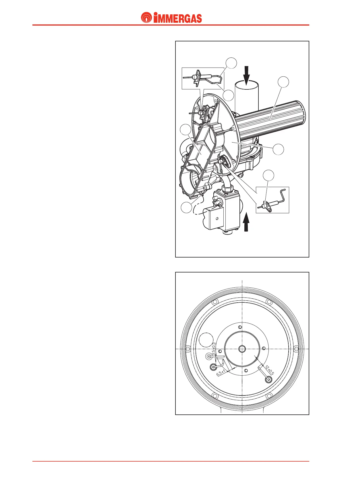
Burner.
is is a cylindrical burner (5) consisting of three concentric
plates appropriately perforated and made of a special stainless
steel highly resistant to high temperatures and corrosion.
It is tted inside the condensation module, in a sealed com-
bustion chamber closed by a ange (6) to which the burner is
secured and which simultaneously ensures direct connection
with the air-gas mix duct (4).
Pre-mixing, the absence of secondary air and the construction
characteristics of the burner ensure high combustion perform-
ance and very low pollutant emissions (see technical data).
anks to the high resistance to temperatures of the materi-
als used, it is possible to operate with a very low ame up
to a minimum output of 18.1 kW (15566 kcal/h) (25 % of
nominal output).
An integrated electronic board sees to ignition and controls
both the ignition (7) and detection (9) electrodes.
Ignition electrodes (7).
ey are controlled by the integrated electronic board which
produces an electrical discharge between them that ignites
the air-gas mix.
Electrode (8) has no ceramic insulation and is earthed directly
(blind electrode).
ey are positioned on the left of the burner and secured on
the ange (6).
Detection electrode (9).
It is controlled by the integrated electronic board and detects
burner ignition.
It also acts as a ue safety device when any air intake or combus-
tion product extraction problems cause the burner to operate
below minimum output.
In this case, in fact, we have a ame-stop condition because
there is no detection by the electrode.
To protect the combustion circuit, this same stoppage prevents
the module from lling with water whenever there are conden-
sation drainage problems (siphon blockage, etc.).
e electrode is mounted on the burner ange (6), at the bot-
tom right of the burner.
Note: in case of ignition block it’s required to check the dis-
tances of the ignition electrodes and of the detection electrodes
sticking to the values shown in the gure at this side.
Check moreover that there are no insulating cinders on the
detection electrodes.
Technical DocumentationTechnical Documentation