9
STV75 ed 01/08 VICTRIX 75
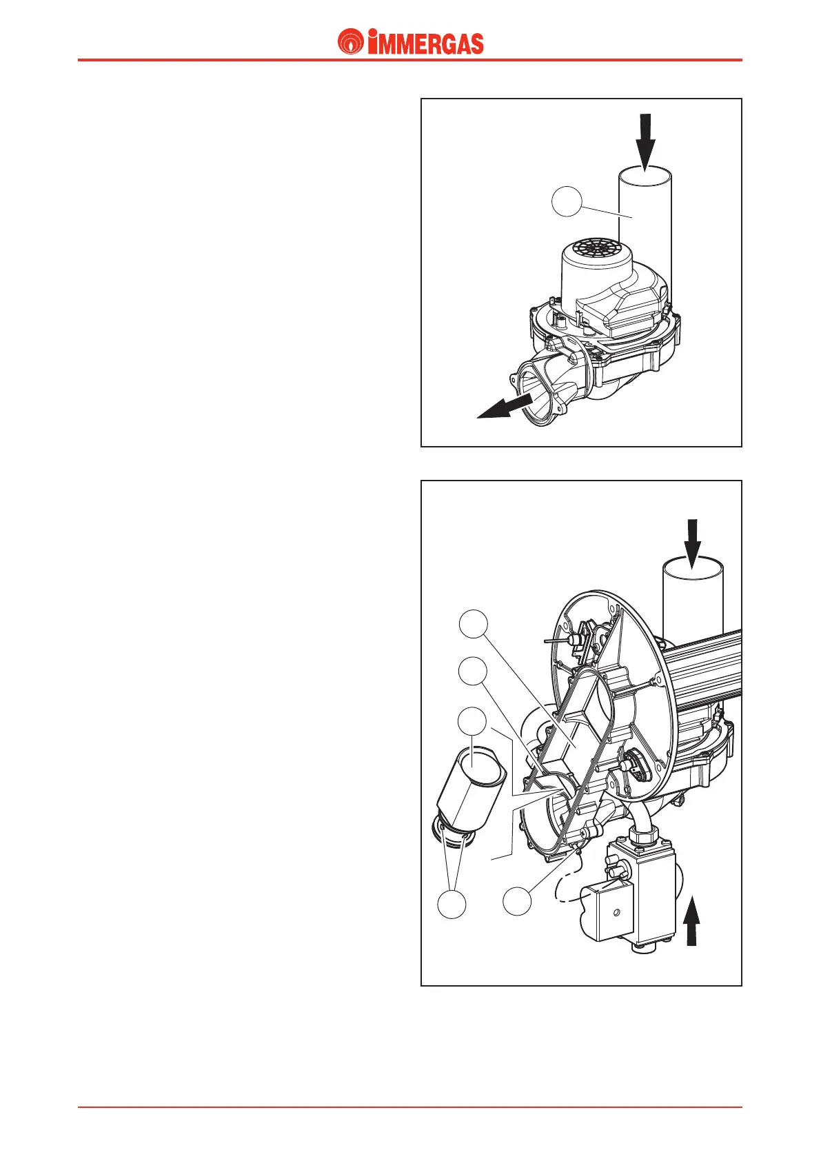
Fan.
is operates upstream from the combustion chamber and it
is physically positioned at the bottom of said chamber.
e fan is powered by mains voltage (230 V AC) and is control-
led by the integrated board by a positive square wave signal
with a variable ON-OFF ratio (duty-cycle).
Its speed is adjusted (from about 1500 to about 5500 rpm) ac-
cording to the output required and is controlled by means of
a Hall eect sensor which reads the rpm.
e fan extracts the combustion air from the top of the draught
diverter through a plastic pipe (1) that helps reduce noise and
optimises burner ignition.
Variations in the ow of air entering the mixing duct results
in a variation in the pressure (P1) signal at the inlet of the
Venturi pipe and enables the pneumatic valve to regulate
exiting gas pressure.
Venturi.
e Venturi pipe (1) is tted in a sealed duct (4) inside which
the combustion air and gas are mixed.
e air is driven to the bottom of the duct by the fan, while
the exiting gas from the valve is injected at the Venturi pipe
(1) inlet by a nozzle (2).
e transit of air in the pipe creates vacuum (“Venturi eect”)
which, through the 4 holes (3) in the base, “drags” the gas
inside and mixes it with the air.
e nozzle (2) diers in diameter according to whether natural
gas or LPG is used; in fact working with both gases at a more or
less constant pressure, its section determines correct gas ow.
At the end of the Venturi pipe is a pressure pick-up point where
the input signal (P1) is read.
is signal is conveyed to the pneumatic valve regulating the
gas pressure via a silicone pipe.
Technical Documentation
Technical Documentation