11
STV75 ed 01/08 VICTRIX 75
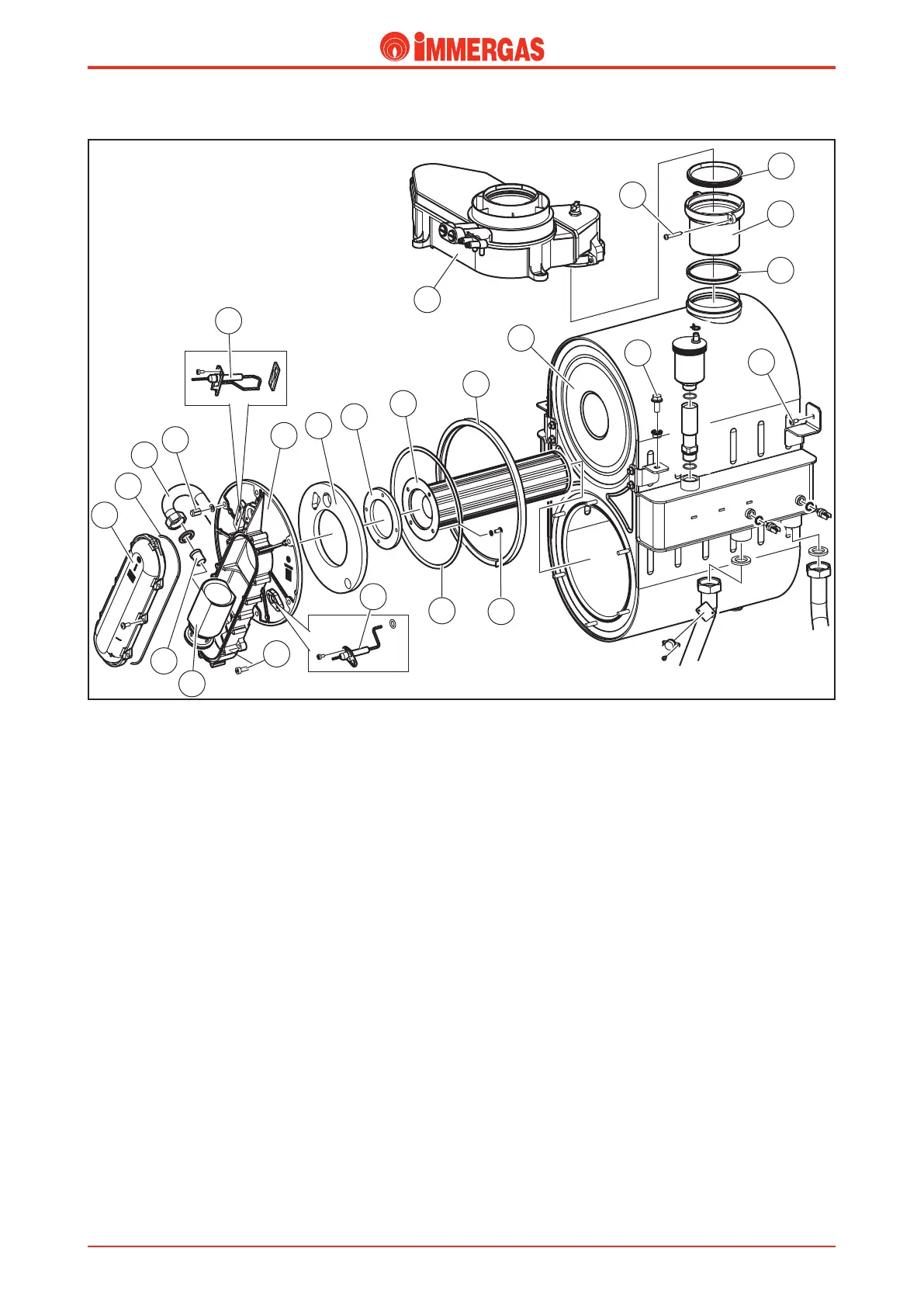
Dismantling main combustion circuit components.
Ensure that the gas valve is closed before dismantling any of
the components.
Replacing the gas nozzle (19).
Loosen the gas pipe (16) to allow access to the gas nozzle (19)
located by the Venturi pipe inlet, then replace the nozzle with
a component of suitable diameter for the type of gas used (see
gas conversion).
N.B.: when retting the nozzle (19), ensure that the gas gasket
is correctly installed.
Dismantling the burner (10).
Loosen the gas pipe (16) and unscrew the two screws (21)
fastening the manifold to the fan, then loosen the 6 blind
nuts (15) fastening the gas manifold ange to the condensa-
tion module (8). To replace the graphite burner gasket (11),
unscrew the 4 screws (24).
N.B.: when retting the burner/manifold assembly, ensure
that the cord packing (23), gas gasket (9), gas pipe gasket (16)
and gasket between the fan ange and gas manifold (13) are
all correctly installed.
Dismantling the condensation module (8).
Drain the water in the module before dismantling.
Undo the nuts fastening the system ow and return pipes and
the condensate drain pipe located underneath the module.
Undo the two screws (7) and (6) fastening the module to the
two triangular mounting cross-pieces (rails), mounted onto
the back of the boiler. Loosen the screw (2) located under the
ue hood and push the stub pipe (4) down to disengage the
ue hood from the condensation module.
N.B.: when reconnecting the ue hood and module, check
the state of the ue gaskets (5) and (3).
Dismantling the ue hood (1).
Undo the three screws fastening the ue hood onto the lateral
mounting cross-piece. Undo the screw (2) located under the
ue hood and push the stub pipe (4) down to disengage the
ue hood from the condensation module.
N.B.: when reconnecting the ue hood and module, check
the state of the ue gaskets (5) and (3).
Dismantling and replacing ignition and detection elec-
trodes.
Undo the two screws fastening the ignition electrode assembly
(14). Undo the two screws fastening the detection electrode
(22).
N.B.: ensure that that the gasket is correctly installed when
retting the ignition electrodes, and ensure that the O-ring
is correctly mounted when retting the detection electrode.
When retting both types of electrode, ensure compliance
with the minimum dimensions specied in the drawing on
the opposite page.
1
13
9
11
12
7
6
10
14
3
4
5
2
8
15
16
17
18
19
20
21
22
23
24
Technical Documentation
Technical Documentation