43
STV75 ed 01/08 VICTRIX 75
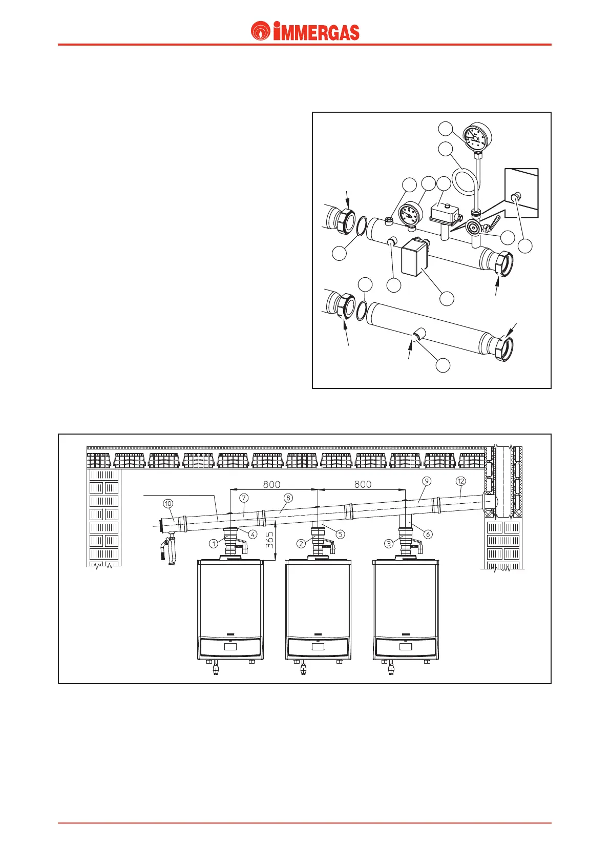
ISPESL safety devices for boilers installed in a
cascade (optional).
With this kit (optional) the ISPESL specications regarding
safety in systems with powers higher than 35 kW are complied
with.
e safety devices and checks consist primarily in an ISPESL
approved thermometer (5), an ISPESL approved manually
reset thermostat (6) and an ISPESL approved manually reset
pressure switch (7).
e contacts of the thermostat (6) and pressure switch (7)
must be installed electrically in series with the boiler’s power
input.
e stub pipes, which are part of the kit, are connected di-
rectly to the boiler’s ow and return manifolds with threaded
elements and, just like the original Immergas hydraulic
manifolds, these too can be installed with the output facing
the right or left.
On the system ow stub pipe it is also possible to mount a
thermometer holder housing device (2) and a probe for the
gas shut-o valve (3). e kit also includes an ISPESL type
approved manometer holder cock element (4) and a ISPESL
approved manometer (11), complete with water hammer
reducing loop (10).
e system return stub pipe, on the other hand, is set for the
connection of an expansion tank that has to be suitable for
system requirements.
Flue manifold for boilers in a cascade (optional).
G3/4"
8
G2"1/2
1
1
G2"1/2
2
5
6
4
9
G2"1/2
G2"1/2
3
7
10
11
e VICTRIX 75 boilers installed in a cascade (battery) in the
B
23
conguration, can be connected, by means of a manifold,
to just the one ue discharge pipe, the couple-on type,
tted with a no-return device (damper), so that the products
of combustion of a working boiler cannot interfere with the
combustion circuit of other boilers that are o.
e system (Green series) is made specically for this type of
appliance with an outside diameter of 125 mm and must lead
into an adequate ue.
e slanting angle of the 125 Ø discharge manifold must be at
least 3° and the condensate water produced by the appliances
must be made to runo into the sewer.
e ue evacuation system cannot be installed outdoors (the
pipes must not be exposed to the ultraviolet rays of the sun).
Note: Check, and adjust if necessary, the heat output of each
single boiler (see handbook and instruction sheet).
Technical Documentation
Technical Documentation