22
STV75 ed 01/08 VICTRIX 75
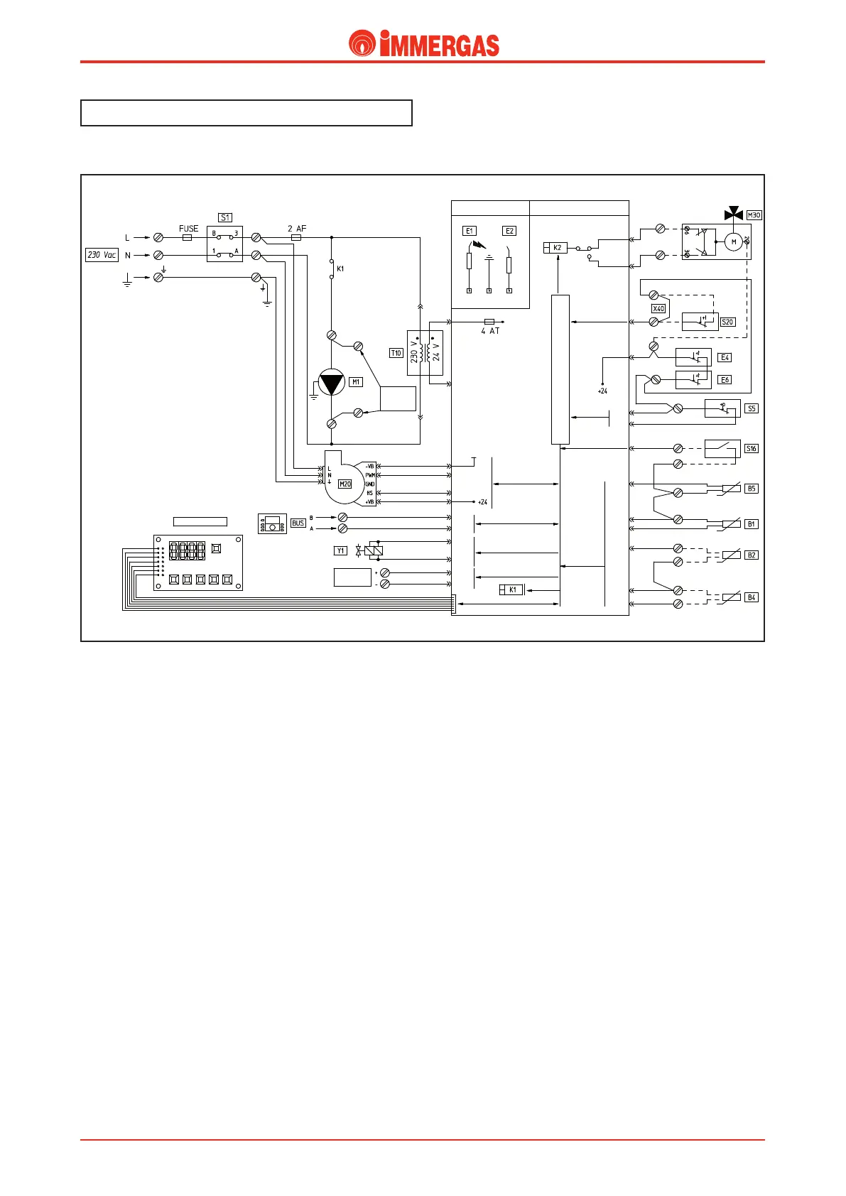
Electrical circuit.
Central heating mode.
Operating with a room thermostat.
When the main switch (S1) is ON it powers the integrated
board, the fan (M20) and enables operation in the central
heating mode.
If the system pressure switch (S5) contact is closed (pressure
detected in the primary circuit higher than the minimum value),
after having obtained the enable from the safety thermostat
(E4) and the ue thermostat (E6) and the room thermostat
contact has closed (S20), the board powers the boiler pump
(M1) by means of relay K1.
In the meantime, the adjustment circuit controls the fan
(M20) speed.
If the temperature measured by the ow NTC probe (B1)
is below the set parameter No. 4 “Central heating ow tem-
perature”, the board enables the start of the ignition cycle,
rst controlling the ignition electrode (E1) and then both gas
valve coils (Y1).
Burner ignition is detected by the board by way of the ioniza-
tion electrode (E2).
Operating with thermoregulation.
Utilising the zones and cascade regulator, the operating request
is controlled by the regulator itself which, depending on the
settings, interacts with the boiler’s integrated board by means
of the BUS cables.
External
circulator
MAX 1 A
IGNITION
DETECTION CIRCUIT
EXTRA LOW VOLTAGE
SAFETY CIRCUIT
BOARD DISPLAY
ANALOGUE
INPUT
Central Heating
D.h.w.
LOGIC COMMANDS MICROPROCESSOR
Technical DocumentationTechnical Documentation