17
STV50 ed 09/08 VICTRIX 50 Rev. 002
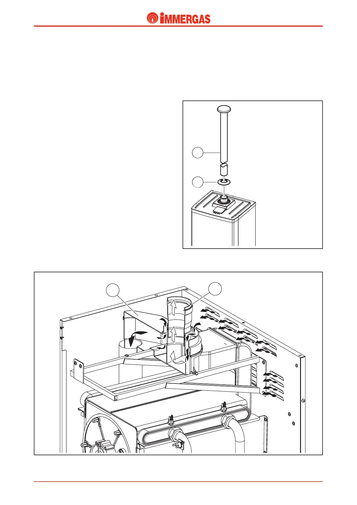
Fan-assisted open chamber conguration.
(type B
23
).
e VICTRIX 50 boilers leave the factory in the B
23
con-
guration.
Air inlet.
e vacuum created by the fan permits the inlet of combus-
tion air through the external concentric hole (125 Ø) of the
draught diverter (1) which is connected to the fan with a
plastic pipe. us the air inlet of air occurs directly from the
room where the boiler is installed through slits at the back of
the boiler and on the side of the valve supporting plate at the
bottom of the boiler.
Exhaust.
Likewise, the products of combustion are expelled through
the narrowest hole (80 Ø) on the draught diverter (1) which
is connected to the exhaust pipes with the adapter (2). us
the ue are discharged outside the room where the boiler is
installed.
Exhaust kit.
e kits with relative accessories permit the use of three 80 Ø
ue discharge systems and a exible 80 Ø ducting system.
As regards the load losses relating to each accessory and the
various possible combinations see the instructions concerning
the exhaust end pieces.
e coupling of the various accessories (curves, extensions, end
pieces) is of the push tting and sealing is ensured by EPDM
peroxide lip seals resistant to the action of condensation.
Inside the kit you will nd:
No. 1 - Washer (1)
No. 1 - 80 Ø exhaust end piece (2)
80 Ø vertical exhaust kit.
Connection to the boiler is done using the vertical 80 Ø ex-
haust end piece (2) in PPS.
Maximum permitted vertical straight length (with no curves)
for the 80 Ø exhaust pipes is 30 metres.
Technical Documentation
Technical Documentation