VICTRIX PRO V2 EU
101
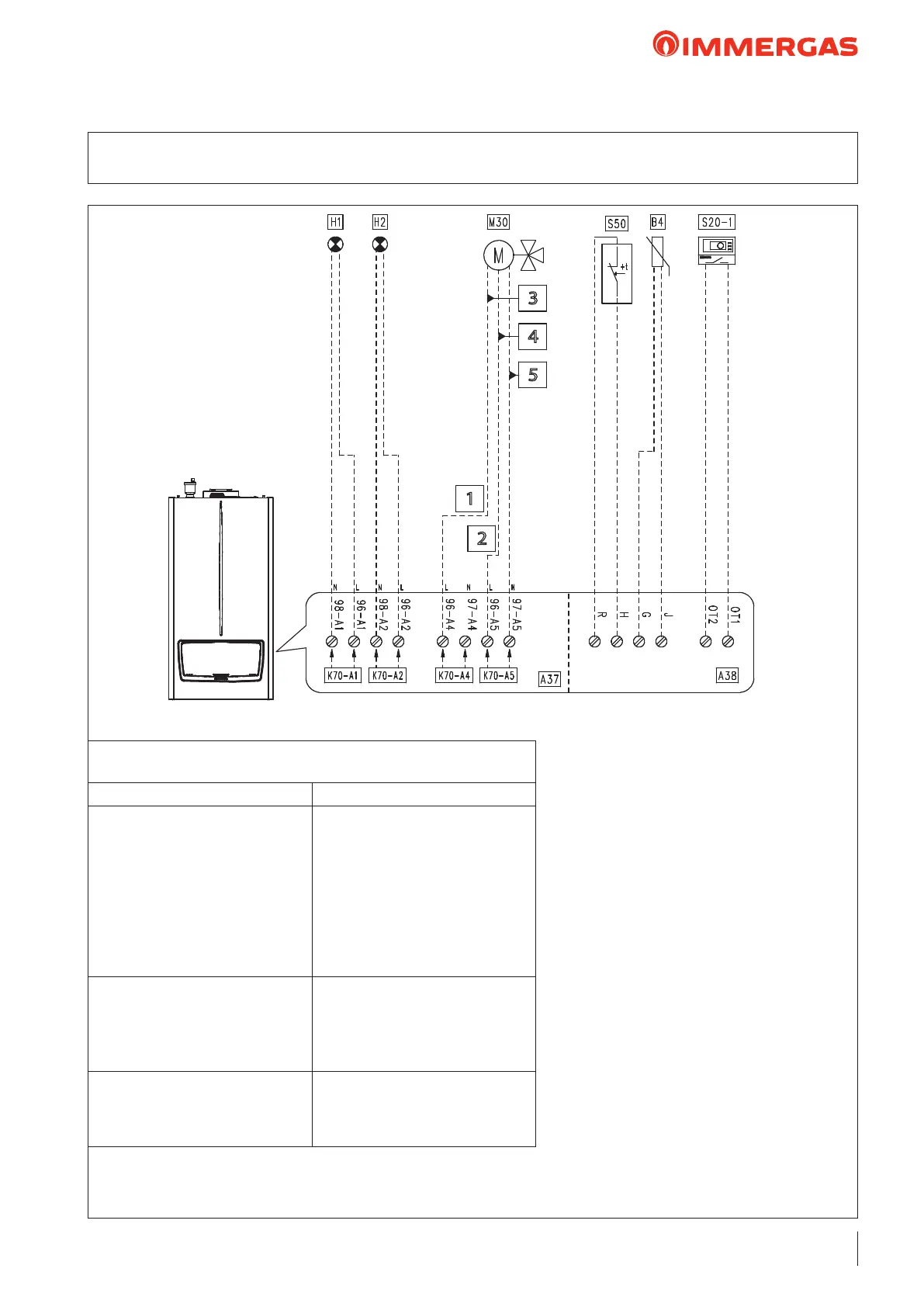
26.6 WIRING DIAGRAM: 3WAY DHW VALVEDHW THERMOSTAT
ONE DIRECT HEATING ZONE
Key:
A37 - Connection sheet (loads)
A38 - Connection card (signals)
B4 - External probe (NTC) (optional)
H1 - "ERROR" indicator light
(230 Vac) (optional)
H2 - “Burner on” indicator light
(230 Vac) (optional)
M30 - 3-way valve (optional)
S20-1 - Zone 1 room thermostat (optional)
S50 - DHW ermostat
1 - Domestic hot water
2 - Central heating
3 - Close
4 - Open
5 - Common
Tabella congurazione parametri
"IMPOSTAZIONI IDRAULICHE" (Menu tecnico)
Nome del parametro/menu Impostazione
“Relay settings” submenu:
- K70-A1
- K70-A2
- K70-A3
- K70-A4
- K70-A5
- K70-A6
- K70-A7
System pump conguration
- Error
- Burner on
- Zone 1 pump
- 3-way valve DHW
- 3-way valve CH
- Relay not used
- Relay not used
- Not used
- System sensor
- Type of heating request
- DHW request type
- Parallel mode
- Not used
- Climatic curve outside temperature
and room thermostat
- ermostat
- Disabled
"3-way valve" submenu:
- 3-way valve selection
- 3-way valve stroke time
- Default position
- Motorised
- 12
- Central heating
3
4
5
1
2
 Loading...