VICTRIX PRO V2 EU
104
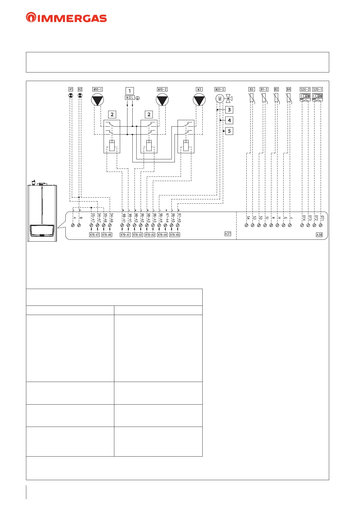
26.9 WIRING DIAGRAM: DHW ZONE HYDRAULIC SEPARATOR
DIRECT ZONE 1 MIXED ZONE 2
Key:
A37 - Connection sheet (loads)
A38 - Connection card (signals)
B1-2 - System ow probe (NTC) (optional)
B2 - Domestic hot water probe (NTC)
(optional)
B3 - Flow probe (Low temperature)
(NTC) (optional)
B4 - External probe (NTC) (optional)
H1 - "ERROR" indicator light
(230 Vac) (optional)
H2 - “Burner on” indicator light
(230 Vac) (optional)
M3 - DHW pump (optional)
M10-1 - Zone 1 circulator pump (optional)
M10-2 - Zone 2 circulator pump (optional)
M31-2 - Mixing valve - zone 2 (optional)
S20-1 - Zone 1 room thermostat (optional)
S20-2 - Zone 2 room thermostat (optional)
1 - 230 Vac - 50 Hz
2 - External relay (optional)
230 vAC coil Max 0,1 A
3 - Close
4 - Open
5 - Common
1
2
3
4
5
2
“HYDRAULIC SETTINGS”
parameter conguration table (Technician menu)
Parameter/menu name Setting
“Relay settings” submenu:
- K70-A1
- K70-A2
- K70-A3
- K70-A4
- K70-A5
- K70-A6
- K70-A7
System pump conguration
- Zone 1 pump
- Zone 2 pump
- Domestic hot water pump
- Mixing valve: closes
- Mixing valve: opens
- Burner on
- Error
- Not used
- System sensor - C.H. + DHW mode
“Mixed zone" submenu:
- Mixed zone selection
- Valve time
- 2
- 150
- Type of heating request
- DHW request type
- Parallel mode
- Climatic curve outside temperature
and room thermostat
- Sensor
- Disabled
 Loading...