1-12
7 - IE
INSTALLATORUSERMAINTENANCE
1.7 INSTALLATION INDOORS.
• Type C conguration, sealed chamber and
forced draught.
Immergas supplies various solutions separately
from the boiler regarding the installation of air
intake terminals and ue extraction; fundamen-
tal for boiler operation.
Important: the boiler must only be installed
together with an origin Immergas air intake
and fume extraction system. is system can
be identied by a special distinctive marking
bearing the note: “not for condensing boilers”.
e fume exhaust pipes must not be in contact
with or near ammable materials and must not
cross building structures or walls made of am-
mable materials.
• Resistance factors and equivalent lengths.
Each flue extraction system component is
designed with a Resistance Factor based on
preliminary tests and specied in the table
below The resistance factor for individual
components does not depend either on the type
of boiler on which it is installed or the actual
dimensions. It is based on the temperature of
uids conveyed through the ducts and therefore
varies according to applications for air intake
or ue exhaust Each single component has a
resistance corresponding to a certain length
in metres of pipe of the same diameter; the
so-called equivalent length, obtained from the
ration between he relative Resistance Factors.
All boilers have an experimentally obtainable
maximum Resistance Factor equal to 100.
The maximum Resistance Factor allowed
corresponds to the resistance encountered with
the maximum allowed pipe length for each
type of Terminal Kit. is information enables
calculations to verify the possibility of various
congurations of ue extraction systems.
Positioning of double lip seals. For correct
positioning of lip seals on elbows and extensions,
follow the assembly direction given in the gure
(Fig. 1-7).
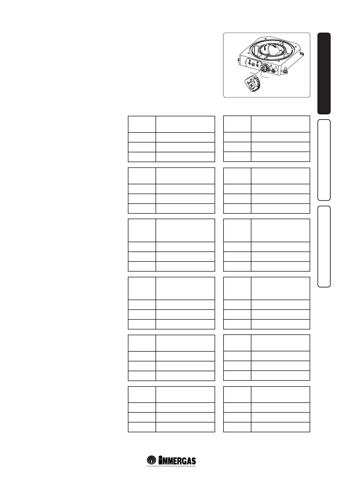
Fumes separator adjustment. For correct
functioning of the boiler the fumes separator
positioned on the air/fumes extraction well must
be adjusted (Fig. 1-12).
Adjustment is carried out by loosening the
front retainer screw and moving the indicator
to the correct position, aligning its value to the
horizontal reference (Fig. 1-12). Once adjustment
has been performed, tighten the screw to x the
separator. Appropriate adjustment takes place on
the basis of the type of pipe and its extension: this
calculation can be carried out using the fumes
separator adjustment tables.
Fumes
separator
*Duct length in metres
Ø 80 horizontal
With two bends
3 From 0 to 4
5 From 4 to 26
6 From 26 to 35
Fumes
separator
Duct length in metres
Ø 80/125 horizontal
3 From 0 to 0,5
5 From 0,5 to 4,6
10 From 4,6 to 7,4
Fumes
separator
Duct length in metres
Ø 80/125 vertical
3 From 0 to 5,4
5 From 5,4 to 9,5
10 From 9,5 to 12,2
Fumes
separator
*Duct length in metres
Ø 80 vertical
without bends
3 Da 0 to 8
5 Da 8 to 30
6 Da 30 to 40
* e values for maximum length are considered
with 1 metre of exhaust pipe and the remaining
on intake.
Fumes
separator
Duct length in metres
Ø 60/100 horizontal
3 From 0 to 0,5
5 From 0,5 to 2
10 From 2 to 3
Fumes
separator
Duct length in metres
Ø 60/100 vertical
3 From 0 to 2,2
5 From 2,2 to 3,7
10 From 3,7 to 4,7
Fumes separator adjustments
Zeus 24 kW.
Fumes separator adjustments
Zeus 28 kW.
Fumes
separator
*Duct length in metres
Ø 80 horizontal
with two bends
3 From 0 to 2
5 From 2 to 21
7 From 21 to 35
Fumes
separator
Duct length in metres
Ø 80/125 horizontal
3 From 0 to 0,5
5 From 0,5 to 4,6
10 From 4,6 to 10,1
Fumes
separator
Duct length in metres
Ø 80/125 vertical
3 From 0 to 5,4
5 From 5,4 to 9,5
10 From 9,5 to 15,0
Fumes
separator
*Duct length in metres
Ø 80 vertical
without bends
3 From 0 to 6
5 From 6 to 25
7 From 25 to 40
Fumes
separator
Duct length in metres
Ø 60/100 horizontal
3 From 0 to 0,5
5 From 0,5 to 2
10 From 2 to 3
Fumes
separator
Duct length in metres
Ø 60/100 vertical
3 From 0 to 2,2
5 From 2,2 to 3,7
10 From 3,7 to 5,7
* e values for maximum length are considered
with 1 metre of exhaust pipe and the remaining
on intake.