11
ACG 0621GB
October 2002
IMO AB, Telephone: + 46 8 50 622 800, Telefax: + 46 8 645 15 09
E-mail: info@imo.se
ACG29 ' IMO AB
H.
Fig. 26
Fig. 28
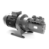
Pressure relief valve
Replacement of O-ring 605
• To avoid changing the setting of the valve, use an
Allen key to prevent spindle 608 to turn.
Unscrew cover 601 and pull up unit 601/608.
• Remove retaining ring 608A and pull the spindle
608 out of cover 601. Replace O-ring 605 and
assemble the unit 601/608 in reverse order.
Replace retaining ring 608A if necessary and
washer 602.
• Fit the unit 601/608 in the valve. Make sure the
608 enters the set screw 612 and use the Allen
key to prevent 608 to turn when cover 601 is
tightened.
Replacement of Valve Element G070
• Release the spring tension by turning the spindle
608 CCW with an Allen key. Use the Allen key to
prevent spindle 608 to turn and unscrew cover
601 but do not remove it yet.
• Remove the set screw 612 by turning the spindle
608 CCW. Pull out the valve piston/spring unit
614/615.
• Fit the valve element in reverse order with a new
washer 602. Turn the spindle 608 CW until the
set screw leave enough room for cover 601. Use
the Allen key to prevent 608 to turn further when
cover 601 is tightened.
• Adjust the valve setting according to the "Instal-
lation and Start-up Instruction for IMO Low
pressure pumps".
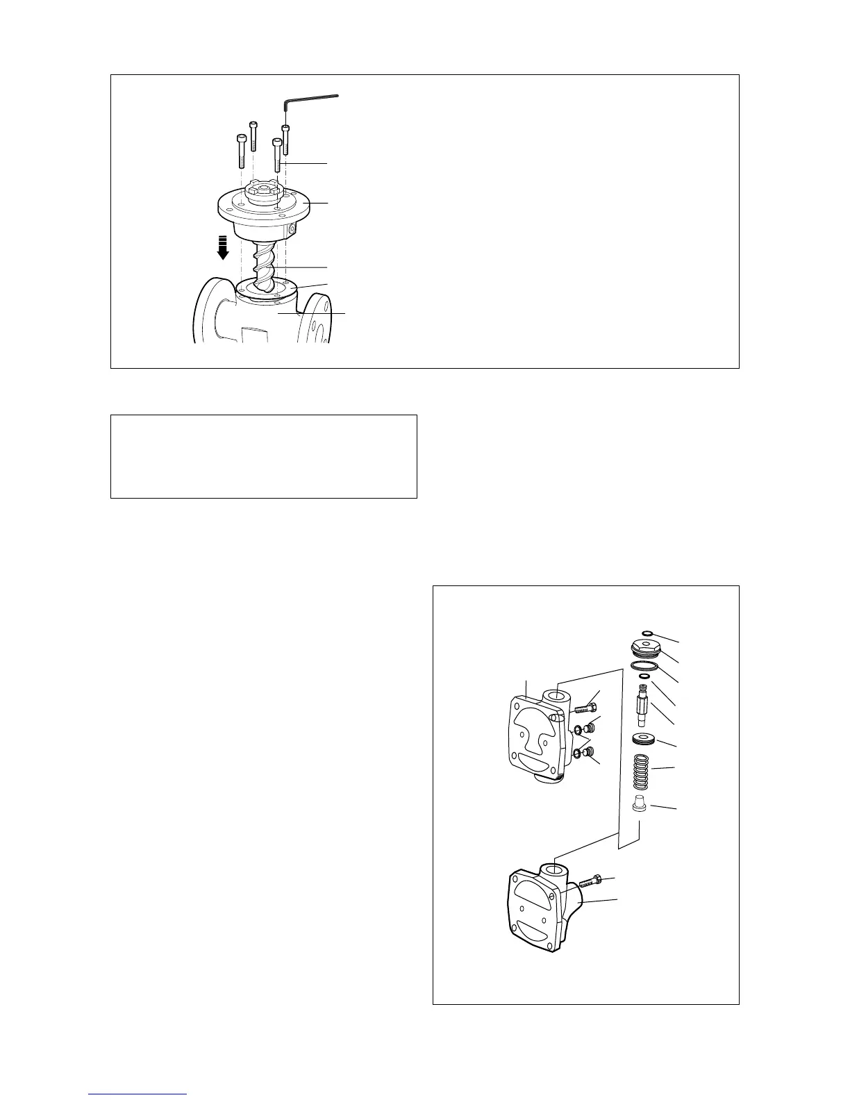
451
5010
1020
506
• Place the gasket 506 on the pump body 401.
• Lubricate the power rotor 1020 and fit the
front cover 5010 together with the rotor set
into the pump body. Mind the position of
the tension pin 545.
• Fit the screws 451 and tighten them cross-
wise.
Version G
Version P
ACG30 ' IMO AB
480
608A
601
602
605
608
612
615
614
453
480
453
462
462A
462
401
Fig. 27
I.
• Put the pump back into the system and
proceed according to instructions under
”Start-up” in the installation manual.