9
ACG 0621GB
October 2002
IMO AB, Telephone: + 46 8 50 622 800, Telefax: + 46 8 645 15 09
E-mail: info@imo.se
ACG22 ' IMO AB
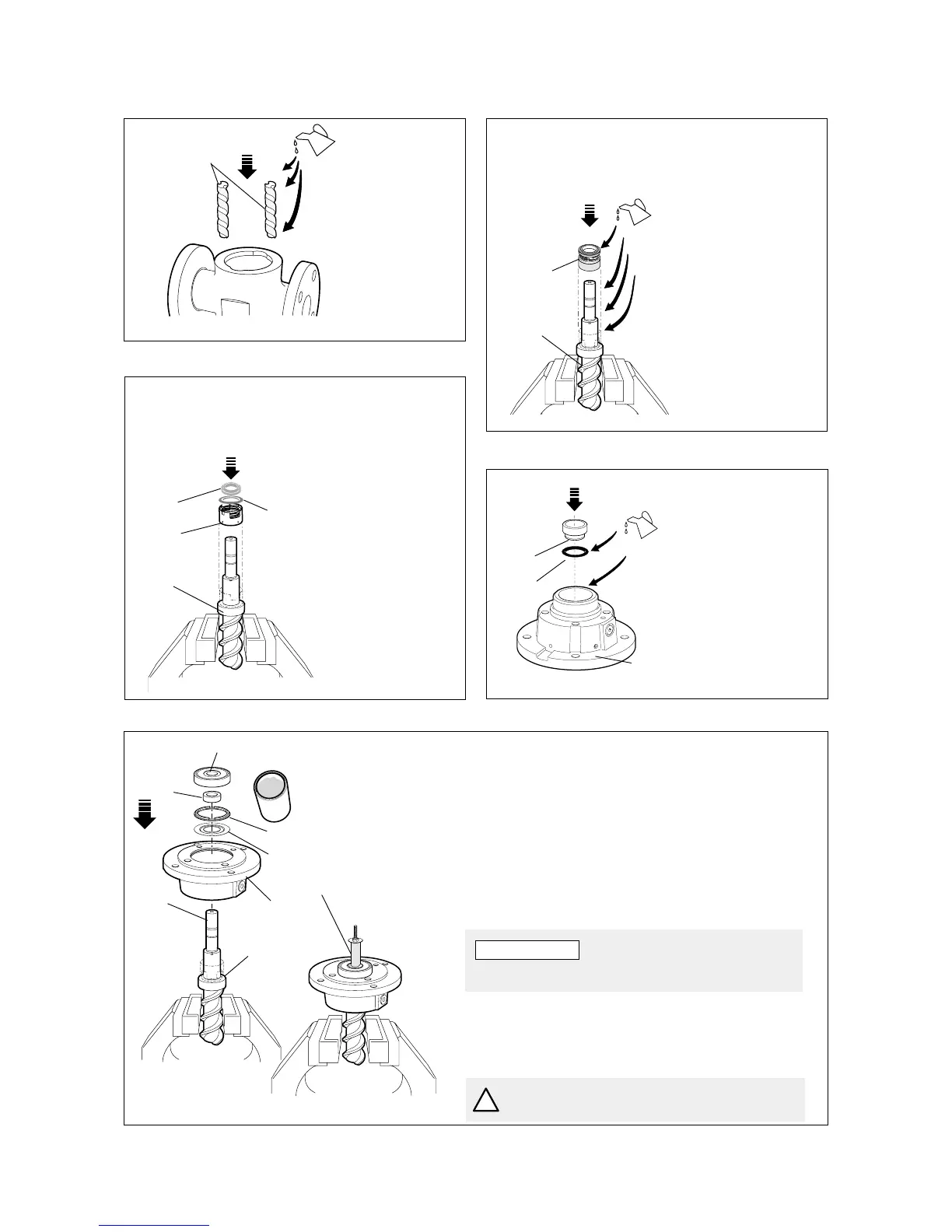
S4
S5
Balance
piston
• Lubricate the
idler rotors and
fit them into the
pump.
Lubrication
groove turned
downwards.
202
A.
Fig. 18
Fig. 20
B–xTxx.
Version xTxx
Reassembly
• Open a package
with a new shaft
seal 509 version
xTxx.
• Place the seal ring
carrier S5 on the
shaft of the power
rotor 1020 flush
against the bal-
ance piston and
lock it with its
stop screws. Fit
the o-ring S6 and
the seal ring S4.
ACG21 © IMO AB
S6
ACG23 © IMO AB
• Carefully place the
power rotor 1020
into the jaw vice
with soft jaws.
• Lubricate all
surfaces of the
power rotor 1020.
• Open a package
with a new sealing
509, version xVxx.
• Place the bellows
unit S5 on the shaft
of the power rotor
and press it down
against the balance
piston (106) (See
fig. 5).
S5
B–xVxx.
Version xVxx
1020
Fig. 19
C.
Fig. 21
• Lubricate the O-
ring S2 and the
recess of the front
cover 5010.
• Clean the sealing
faces and fit the
seat S1 into the
front cover 5010.
Mind the position
of the retaining
pin if applicable.
S1
S2
ACG24 © IMO AB
5010
D.
• Lubricate the balance piston 106 with a thick oil (ISO VG 460).
• Fit the front cover onto the power rotor 1020 untill it rests on
the bellows unit S5.
• Fit the support ring 359A and the distance washer 359 into the
front cover. Mind the position of the distance washer 359.
• Fit the distance sleeve 120 into the front cover 5010.
• Fill the ball bearing with appropriate grease. See page 5 for
grease selection.
• Fit the ball bearing 122 onto the shaft.
359
359A
5010
Grease
120
1020
122
Mounting kit
106
Fig. 22
ATTENTION
The open side of the bearing towards the cover.
• Fit the mounting sleeve and push the bearing to
its final position in the front cover. To do this
some force is required. Use Your column drilling
machine or mounting kit (see fig 4).
!
Do not use a hammer etc. as this might
damage the shaft seal and ball bearing.