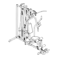
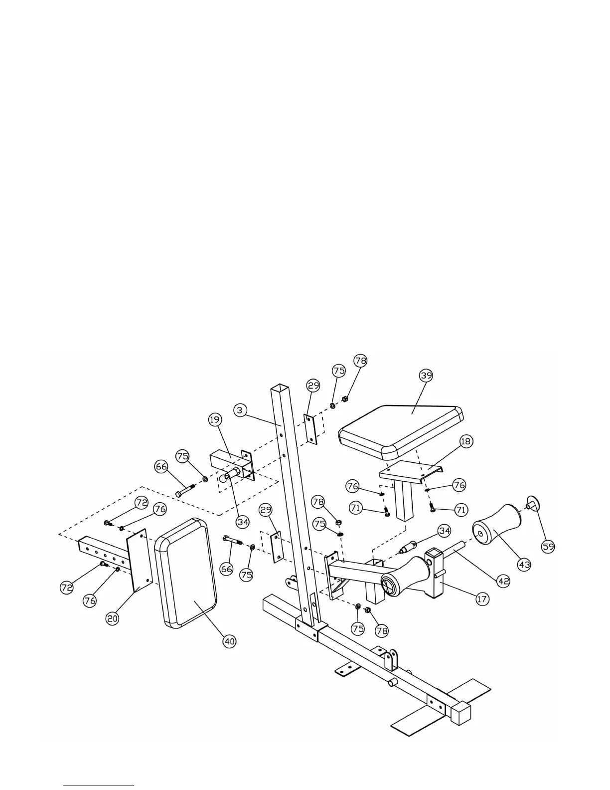
STEP 4 (See Diagram 4)
A.) Attach the Leg Developer Holder (#17) to the Front Vertical Frame (#3). Secure it with two
M10 x 3” Hex Bolts (#66), four ∅ 13/16” Flat Washers (#75), one 2” x 4 ¾” Bracket (#29),
and two M10 Aircraft Nuts (#78).
B.) Attach the Short Quick Release Pin (#34) to the Leg Developer Holder (#17).
C.) Attach the Seat (#39) to the Seat Support (#18). Secure it with two ∅ 11/16” Flat Washers
(#76), and two M8 x 2 9/16” Allen Bolts (#71).
D.) Attach the Seat Support (#18) to the Leg Developer Holder (#17). Pull the Short Quick
Release Pin (#34) to adjust the height of the Seat.
E.) Insert a Foam Roll Tube (#42) halfway through the hole on Leg Developer Holder (#17).
Push two Foam Rolls (#43) onto the Tube from both ends. Push two ∅ 3” Round Plugs (#59)
onto both ends of the Tube.
F.) Attach the Backrest Support Frame (#19) to the Front Vertical Frame (#3). Secure it with two
M10 x 3” Hex Bolts (#66), four ∅ 13/16” Flat Washers (#75), one 2” x 4 ¾” Bracket (#29),
and two M10 Aircraft Nuts (#78).
G.) Attach the Short Quick Release Pin (#34) to the Backrest Support Frame (#19).
H.) Attach the Backrest (#40) to the Backrest Adjustment Tube (#20). Secure it with two ∅
11/16” Flat Washers (#76) and M8 x 5/8” Allen Bolts (#72). Insert the Backrest Adjustment
Tube (#20) into the Backrest Support Frame (#19). Pull out the Quick Release Pin (#34) to
adjust the Backrest position.
DIAGRAM 4
7