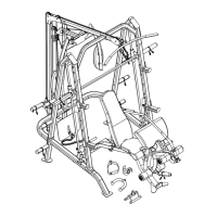
STEP 3 (See Diagram 3)
A.) Attach the Weight Glide Post (#5) to the bracket on the Rear Vertical Frame Base (#7).
Secure it with two M10 x 2” Carriage Bolts (#72), Ø ¾” Washers (#86), and M10 Aircraft
Nuts (#83).
B.) Slide the Sliding Weight Post (#22) onto the Weight Glide Post from the top. Make sure
the Cable connecting bracket on the Sliding Weight Post faced up.
C.) Attach the rear of the Upper Frame (#11) to the top of the Weight Glide Post (#5). Secure
it with two M10 x 2” Carriage Bolts (#72), Ø ¾” Washers (#86), and M10 Aircraft Nuts
(#83).
D.) Attach the Upper Frame to the Rear Vertical Frame (#6). Secure it with one M10 x 2”
Carriage Bolt (#72), Ø ¾” Washer (#86), and M10 Aircraft Nut (#83).
E.) Attach each end of the two Upper Support Frames (#9) to the two Front Vertical Frames
(#2). Secure each Upper Support Frame with one 4” Bent Bracket (#30), M10 x 3 ½” Allen
Bolt (#79), and Ø ¾” Washer (#86) to the top hole. Secure the bottom hole with one M10
x 3 ½” Carriage Bolt (#69), Ø ¾” Washer (#86), and M10 Aircraft Nut (#83).
F.) Attach the Upper Support Frames (#9) to the Upper Frame (#11) from each side. Align the
holes and secure them together with two M10 x 2” Carriage Bolts (#72), Ø ¾” Washers
(#86), and M10 Aircraft Nuts (#83).
G.) Securely tighten all Nuts and Bolts previously installed.
11