ASSEMBLY INSTRUCTION
Tools Required Assembling the Machine: Two Adjustable Wrenches and Allen Wrenches
NOTE: It is strongly recommended two or more people assembling this machine to avoid
possible injury.
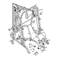
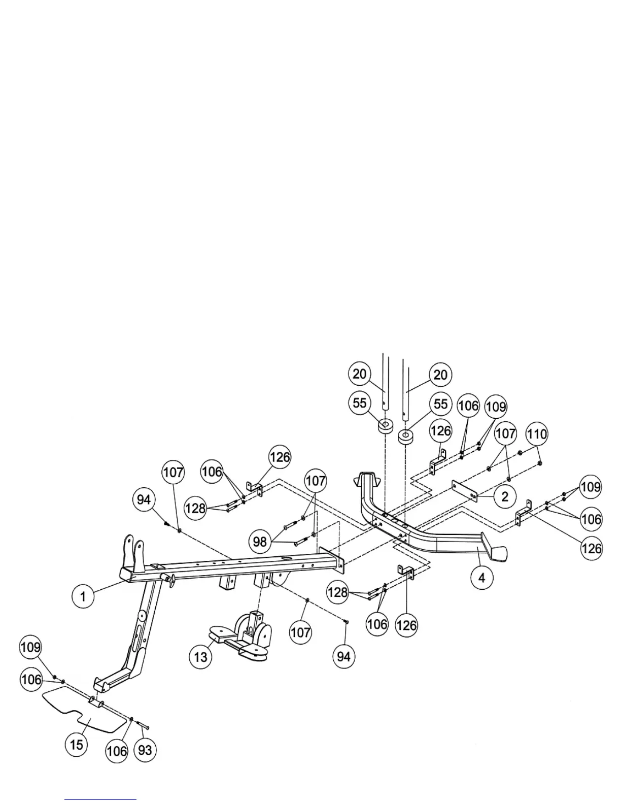
STEP 1 (See Diagram 1)
A.) Attach the Butterfly Pulley Bracket (#13) to the Main Support Frame (#1) from the bottom. Secure
it with two M10 x ¾” Allen Bolts (#94) and two Ø ¾” Washers (#107).
B.) Place the two Rubber Bumpers (#55) onto the holes on the Rear Base Frame (#4). Insert the two
Guide Rods (#20) through the Rubber Bumpers into the holes on the Rear Base Frame.
C.) Attach the Main Support Frame (#1) to the Rear Base Frame. Secure it with two M10 x 3” Allen
Bolts (#98), one Bracket (#2), four Ø ¾” Washers (#107), and two M10 Aircraft Nuts (#110).
Rotate the Guide Rods to align the holes so the bolts can go through.
D.) Install four Weight Stack Cover Brackets (#126) to the Rear Base Frame. Secure the Brackets
with four M8 x 2 ¾” Allen Bolts (#128), eight Ø 5/8” Washers (#106), and eight M8 Aircraft Nuts
(#109).
E.) Attach the Foot Plate (#15) to the front base on the Main Support Frame. Align the holes and
secure it with one M8 x 3” Allen Bolt (#93), two Ø 5/8” Washers (#106), and one M8 Aircraft Nut
(#109).
DIAGRAM 1
10