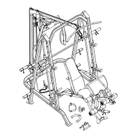
STEP 10 (See Lower Cable Loop & Diagram 10)
A.) Attach the 184” Lower Cable (#45) to the open bracket on the Leg Developer (#6). Attach a
Pulley (#59) to the bracket. Secure it with one M10 x 1 ¾” Allen Bolt (#95), two ∅ ¾”
Washers (#107), and one M10 Aircraft Nut (#110).
B.) Draw the Cable to the opening on the Main Support Frame (#1). Attach a Pulley to the
opening. Secure it with one M10 x 2 ¾” Allen Bolt (#97) and one M10 Aircraft Nut (#110).
C.) Draw the Cable through the opening on the Butterfly Pulley Bracket (#13) to the open
bracket under the Main Support Frame.
D.) Attach a Pulley to the open bracket. Secure it with one M10 x 1 ¾” Allen Bolt (#95), two ∅
¾” Washers (#107), and one M10 Aircraft Nut (#110).
E.) Draw the Cable to the open bracket on the Double Floating Pulley Bracket (#16) previously
installed in Step 9. Repeat Procedure D above to install a Pulley. Draw the Cable around the
Pulley then downward.
F.) Attach the Cable to another Double Floating Pulley Bracket. Repeat Procedure D above to
install a Pulley. Draw the Cable around the Pulley then upward. Let the Double Floating
Pulley Bracket hanging for now.
G.) Draw the Cable to the Upper Frame (#17). Attach a Pulley to the hole on the right side of the
Upper Frame. Secure the Pulley to the Upper Frame with M10 x 4 3/8” Allen Bolt (#102),
one Round Pulley Bracket (#39), two Ø ¾” Washers (#107), and one M10 Aircraft Nut
(#110).
H.) Draw the Cable around the Pulley then downward. Connect a Short Chain (#88) to the
Cable with a Hook (#89). Attach a Hook to the other end of the Short Chain. Let the Short
Chain hanging for now.
24