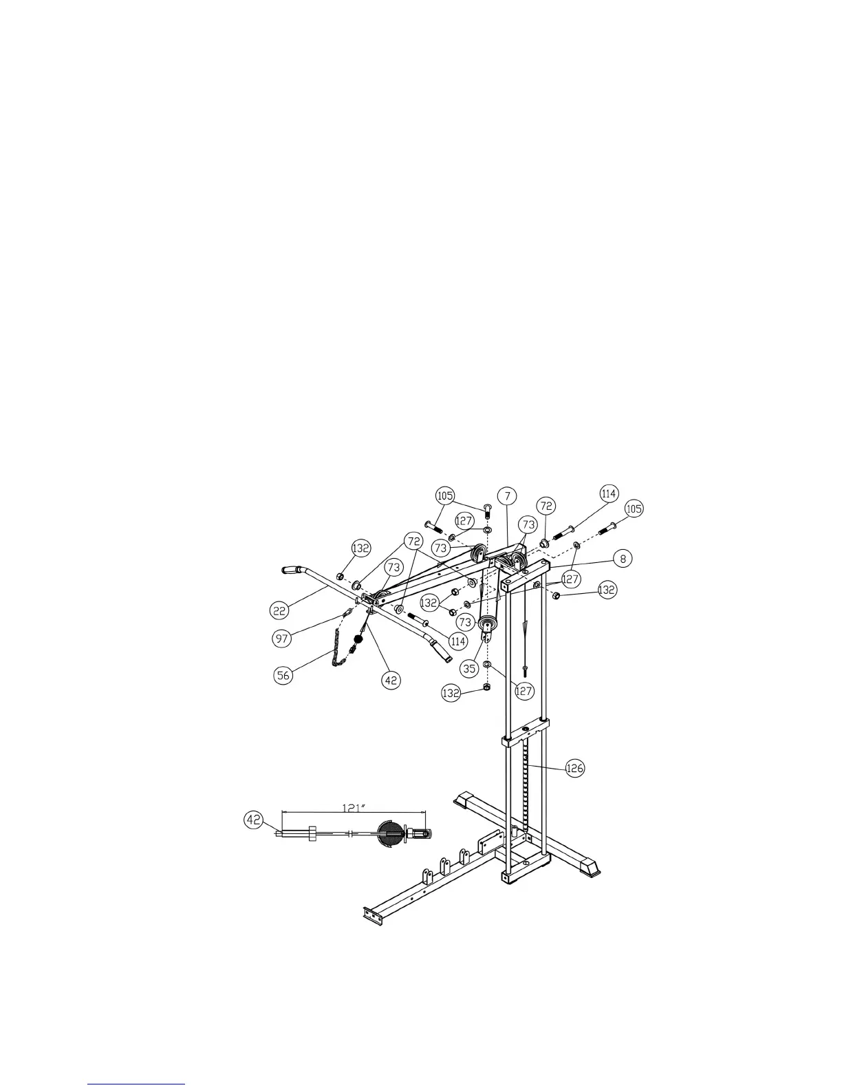
A.) Attach the 121” Upper Cable (#42) to the front of the Upper Frame (#7). Install a Pulley (#73).
Secure it with one M10 x 2 ½” Allen Bolt (#114), two ∅3/8” Bushings (#72), and one M10
Aircraft Nut (#132). Make sure the Rubber ball on the Cable is underneath the Frame. Slide
the Bolt on the Cable to the other end. Use Quick Release Connector (see How To Use) to
connect Short Chain (#56) to the Cable. Use a Clip (#97) to connect the Lat Bar (#22) to Short
Chain (#56).
B.) Draw the Cable towards the back of the machine to the bracket on the top of the Upper Frame
(#7). Install a Pulley (#73). Secure it with a M10 x 1 ¾” Allen Bolt (#105), two ∅ ¾” Washers
(#127), and a M10 Aircraft Nut (#127).
C.) Pull the Cable downward through the opening on the Upper Frame. Install a Pulley (#73) and
an Angled Double Floating Pulley Bracket (#35). Secure it with a M10 x 1 ¾” Allen Bolt
(#105), two ∅ ¾” Washers (#127), and one M10 Aircraft Nut (#132). Let the Bracket hanging
for now.
D.) Pull the Cable upward to the Top Socket Assembly (#8). Install a Pulley. Secure it with a
M10 x 2 ½” Allen Bolt (#114), two ∅3/8” Bushings (#72), and one M10 Aircraft Nut (#132).
E.) Continue drawing the Cable to the bracket on the top of the Top Socket Assembly (#8). Install
another Pulley. Secure it with a M10 x 1 ¾” Allen Bolt (#105), two ∅ ¾” Washers (#127), and
one M10 Aircraft Nut (#132).
F.) Pull the Cable over the Pulleys then through the hole on the Top Socket Assembly (#8) down
to the Selector Rod (#126). Screw the Bolt on the end of the Cable into the Selector Rod.
DIAGRAM 9
12
STEP 9 (See Diagram 7 & 10)
A.) Attach the ball-end of the 171” Ab Cable (#45) to the opening on the Front Vertical Beam (#6).
Install a Pulley. Secure it with a M10 x 2 ½” Allen Bolt (#114), two ∅3/8” Bushings (#72), and
 Loading...