Speedway Revolution Installation and Operations Guide
23 Copyright © 2009, Impinj, Inc.
Appendix B: GPIO Details
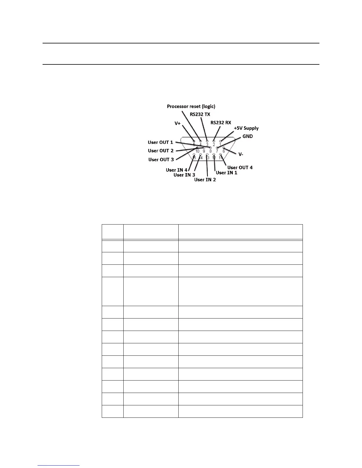
The following graphic shows the detailed function of each pin of the GPIO DB-15 connec-
tor.
Figure 2: DB-15 GPIO Port
Note:
Both the input and output pins are opto-isolated.
The following tables further explain the function of each pin.
Table 5: DB-15 Connector Pin-Out
Pin I/O Name I/O Function
1 +5V Supply Reader supplied (not isolated) power source
2 RS-232 RX For auxilliary serial port functions
3 RS-232 TX For auxilliary serial port functions
4 Processor Reset A hard reboot into the reader
(Pulling this line low performs the same function as
pressing the FDR button—see Table 2 on page 6 for
details.)
5 V+ Power source for isolated outputs
6 V- Return for isolated inputs and outputs
7 Ground Reader (not isolated) return
8 User OUT 1 Isolated output 1 (active pull down to V-)
9 User OUT 2 Isolated output 2 (active pull down to V-)
10 User OUT 3 Isolated output 3 (active pull down to V-)
11 User OUT 4 Isolated output 4 (active pull down to V-)
12 User IN 1 Isolated input 1
13 User IN 2 Isolated input 2
 Loading...