Speedway Revolution Installation and Operations Guide
5 Copyright © 2009, Impinj, Inc.
Chapter 2: Installing and Connecting
Speedway/Revolution
This chapter provides details about the Speedway/R I/O ports and status LEDs and
explains the detailed procedures for installing the reader and connecting it to your net-
work.
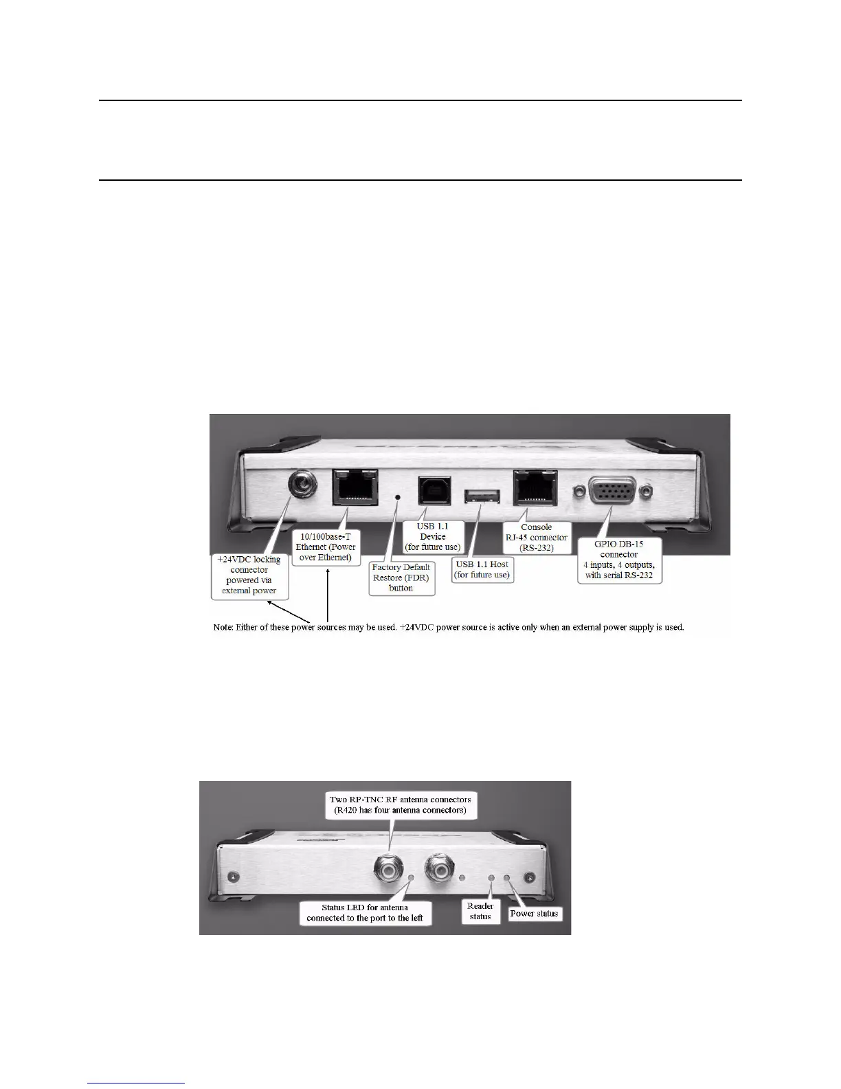
Speedway/R I/O Ports and Status LEDs
The following graphic illustrates the various I/O ports located on the Speedway/R reader.
This graphic illustrates a Speedway R420, which includes four antenna ports (not visible
in this graphic). Note that Speedway R220 includes two antenna ports. Other than that dif-
ference, however, the exterior ports are the same on both models.
Figure 1: Impinj Speedway/R Port Connections
Note:
For details on the function and electrical specifications for each pin of the GPIO DB-15
connector, see “Appendix B: GPIO Details” on page 23.
Antenna Ports and Status LEDs
On the back side of the reader are the antenna ports and LED status indicators. The follow-
ing graphic (of an R220) illustrates their locations: