Assembly
17
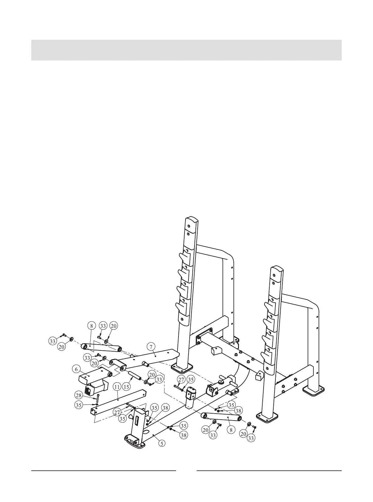
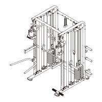
STEP 2
1. Attach the Sliding Rack ASSY (#6) to the Adjustable Tube ASSY (#11).
2. Attach the Adjustable Tube ASSY (#11) to the Main Frame ASSY (#5) using:
two M10*75 SHCS (#27) one M10*70 SHCS (#28)
six Φ11*Φ20*2 Flat Washer (#35) three M10 Nylon Lock Nut (#38)
3. Attach the Back Pad Frame (#7) to the Sliding Rack ASSY (#6) using:
two M10*30 FHCS(#33) two Cap Φ38*Φ10.5*8 (#20)
one shaft Φ25.4*146 (#15)
4. Attach two Support Frame ASSYS (#8) to the Main Frame ASSY (#5) and the Back Pad
Frame (#7) using:
four M10*30 FHCS(#33) four Cap Φ38*Φ10.5*8 (#20)
Note: NOT Tighten Bolts and Nylon Lock Nuts.