ImpulseRadar
CrossOver® User Manual V1.4
Page 13 (31)
• Time Interval – defines the Time between every A-scan
1
when Trig source is set to Time.
• Soil Velocity – defines the velocity used to calculate the depth scale.
• Number of Samples – defines the time window, or maximum penetration depth, and the
adjacent Max Depth is calculated based on the Soil Velocity.
• Data Mode – defines how many bits are used while storing the resulting radar data.
CrossOver® antennas, below 600 MHz, can provide more than 16-bits, so 32b can be selected.
The precise number of useful bits depends on the point distance, survey speed and antenna
frequency. A lower antenna frequency combined with slower speed and larger point distance,
provides a higher number of useful bits. The limit today is approx. 19-20 useful bits. Note that
using 32 bits during surveys requiring high speed only increase the risk of dropping data in the
WIFI-link, use 16 bits and not unnecessary long time-windows to reduce load on data
transmission in these cases.
• GPS – defines whether to use the internal module or an externally connected system. If
External is selected, you must adjust for the correct baud-rate, which can be obtained from
the user manual for the GPS system used. EXT + TP is intended for use with an external while
gathering precise time-stamping on each A-scan with help of the internal GPS. If no external
GPS is present, when this option is selected, a time-sync file will still be created. See also later
paragraph on GPS-symbols.
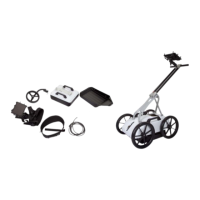
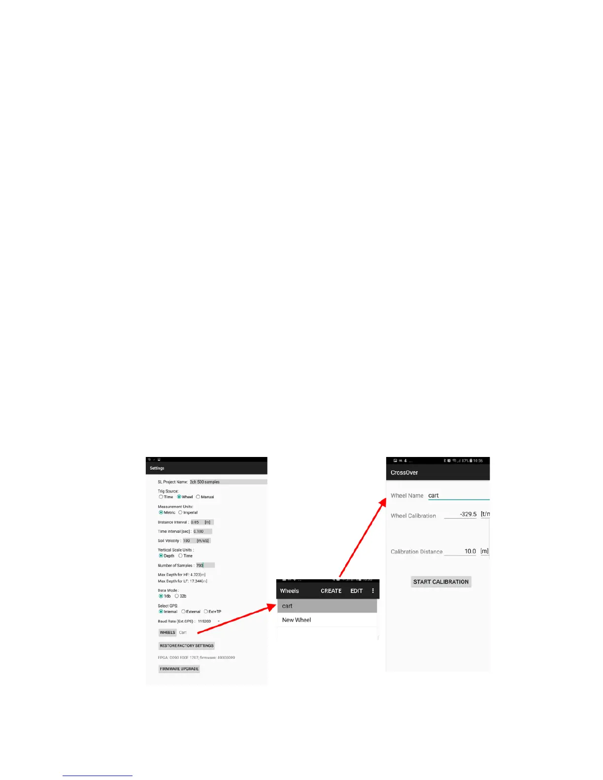
• Wheels – defines the type of wheel connected to the antenna for distance measurement.
Standard wheel options include Cart and Single, but you may create additional wheels and/or
adjust wheel calibration settings as described in the ‘wheels’ section below.
• Restore factory settings – If internal settings has been corrupted or after a firmware upgrade,
it’s advisable to restore to factory settings, all essential system parameters will be reset to
initial state.
• Firmware upgrade - Menu trough which upgrade of firmware may be done, see later
paragraph.
1
An A-scan is the envelope, or trace, formed by connecting all the samples collected at one specific point along the survey line.
Figure 12, Settings menu and two of its child-menus, wheel selection and calibration