ImpulseRadar
CrossOver® User Manual V1.4
Page 5 (31)
For information on other applications and/or configurations, please contact your local ImpulseRadar
representative, or contact our sales team at: sales@impulseradar.se
Antennas
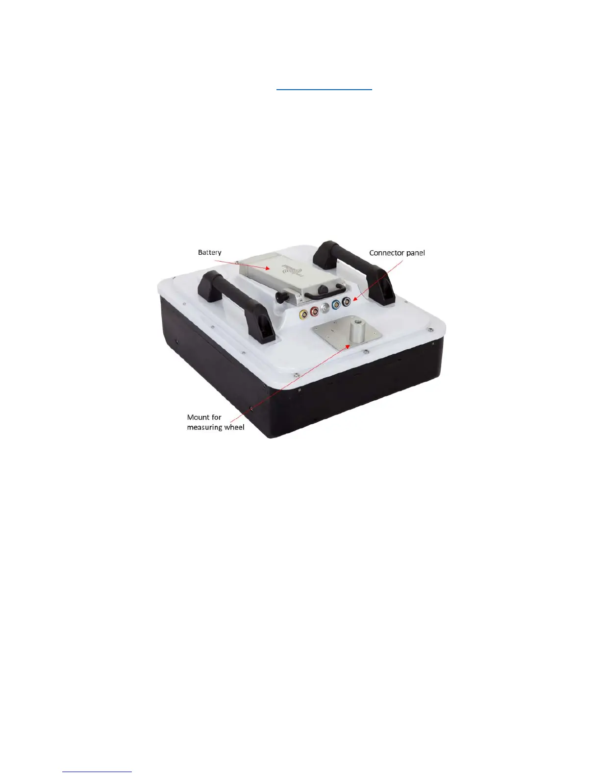
Apart from physical size, CrossOver® antennas share a similar mechanical design and the same
arrangement for the battery, connector panel and measuring wheel mount. A CO4080 antenna is used
to highlight these features, as shown below in Figure 2.
Regardless of model, each Crossover® antenna includes inbuilt WiFi and a high-quality differential GPS
receiver (Ublox/Tallysman). There is no external connection to these components, although markings
on the housing showing their approximate internal location.
Figure 2 CO4080 antenna with battery attached
Connector panel
Refer to the arrangement shown in Figure 2:
• Yellow – Kill switch. In certain countries, a GPR device used on walls should have a kill-switch.
If required, this connector allows the connection of an external kill switch.
• Red – Power and Ethernet. A battery is the preferred way of powering the antenna; however,
an optionable power cable is available upon request. This connector is also used for testing
and factory upgrades via Ethernet.
• Silver – On/Off button. Press the button once for approx. 2s to switch the antenna on. When
on, the button glows blue. A subsequent press will switch the antenna off.
• Blue – External GPS. Allows the connection of an external GPS antenna to provide higher
precision positioning. Communication is based on RS232 and the NMEA 0183, V2, protocol.
• Black – Measuring wheel. Note, this connector is placed further back on the lower frequencies.
All cable-connectors are high-quality Yamaishi-type. Cable-connectors are inserted/removed by
holding the connector sleeve then gently pushing or pulling straight without turning. The connectors
are keyed so that it’s not possible to damage the unit by attaching a cable to the wrong connector.