Do you have a question about the IMST iM871A and is the answer not in the manual?
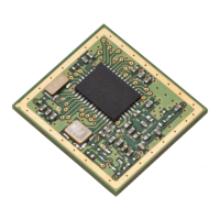
Compact module, low power, multiple interfaces (UART, SPI, I²C), digital/analog I/O, voltage range.
Smart metering for water, heat, electricity, gas meters and data concentrators.
Explains the layered architecture of the Wireless M-Bus protocol stack.
Introduces the Wireless M-Bus protocol stack compliance with EN 13757-4.
Lists and describes supported Wireless M-Bus link modes (S, T, R, C) and their parameters.
Specifies UART baud rate, data bits, stop bit, and parity for communication.
Explains the message-based serial protocol for configuration, data exchange, and control.
Covers functions like Ping Request and Reset Request for device interaction.
Explains different System Operation Modes like Application and Hardware Test Mode.
Details the embedded RTC for timer-controlled operations and setting/getting time.
Describes the automatic power saving mode for meter devices after sending a WM-Bus message.
Details the configuration of port pins for Alive, TX, and RX indicators.
Describes the general radio configurations, including channel and power level settings.
Lists the available RF channels and their corresponding frequencies in R-Mode.
Shows the possible power level settings and their corresponding TX power in dBm.
Explains the timing diagram for waking up from low power mode and subsequent operations.
Provides an overview of the demo board and its peripherals for mounting the iM871A.
Describes the USB interface for PC communication and necessary driver installation.
Details the installation of hardware drivers for the USB controller on the PC.
Provides a list of abbreviations used throughout the document with their full meanings.
Lists all tables included in the document with their corresponding page numbers.
States that information is provided "as is" without guarantee and reserves rights to make changes.
Provides IMST GmbH's contact details, including address, phone, fax, email, and website.
| Manufacturer | IMST GmbH |
|---|---|
| Type | Wireless M-Bus Module |
| Frequency Range | 868 MHz |
| Modulation | FSK |
| Output Power | up to 14 dBm |
| Data Rate | up to 100 kbps |
| Interface | UART |
| Operating Voltage | 2.7 V to 3.6 V |
| Temperature Range | -40°C to +85°C |
| Operating Temperature | -40°C to +85°C |