User Manual
iM871A Wireless M-Bus Module Specification
iM871A_WMBus_UserManual.docx, Wireless Solutions, v1.2 Page 19
4.1.3 Data Rate Setup
Table 4-3 shows the used RF data rates setups. They are configured automatically by the
module firmware dependent on the selected Wireless M-Bus mode, the Device Mode and the
data direction.
chip rate, results in a data rate of 2.4 kbps (Manchester coding)
chip rate, results in a data rate of 16.384 kbps (Manchester coding)
chip rate = data rate (NRZ coding)
chip rate, results in a data rate of 66.66 kbps (3 out of 6 coding)
chip rate = data rate (NRZ coding)
Table 4-3: Possible RF Data Rates
4.2 System Timing
4.2.1 Wake-up after Low-Power-Mode
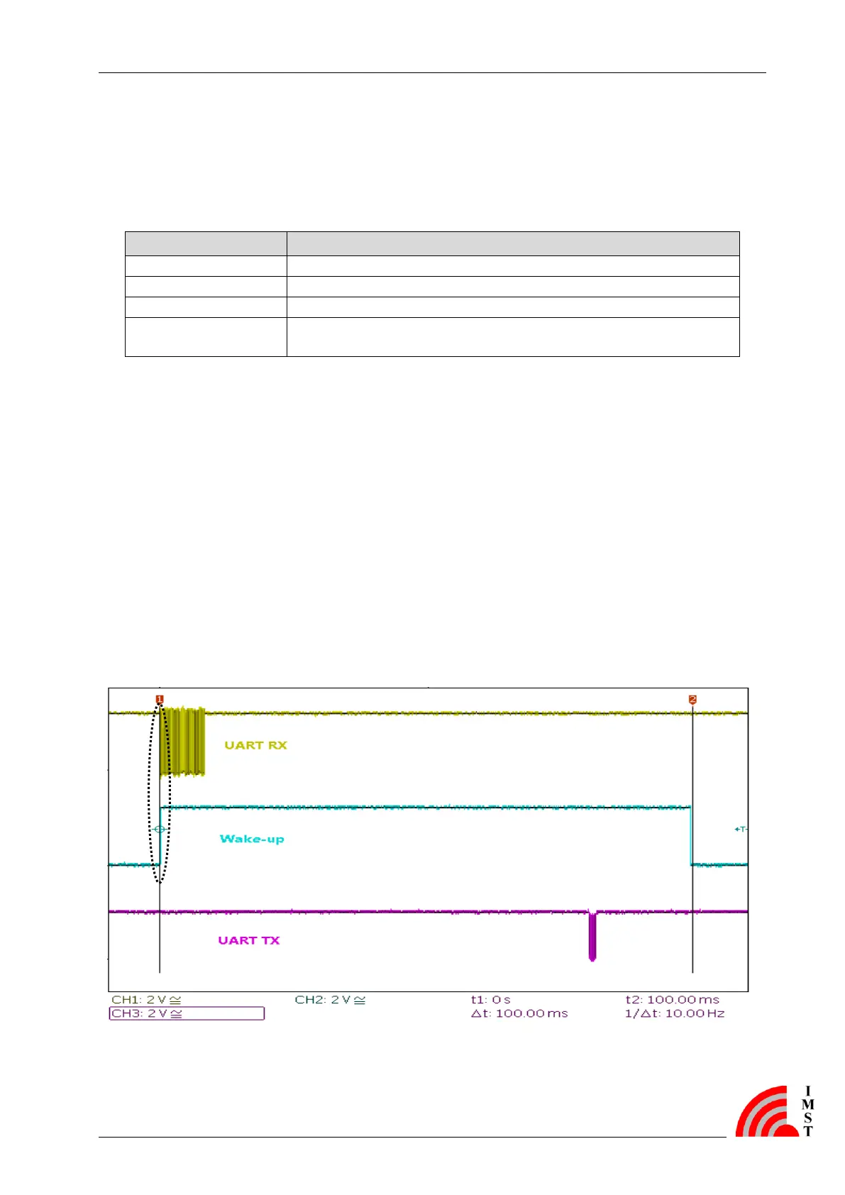
Figure 4-1 shows the timing diagram of the transmission of a 42 byte WM-Bus packet in S-
Mode. The device is in Low Power Mode and is woken up by the edge of the first UART bit
that is received from the host controller. After successful RF transmission, the host controller is
informed with a status message. Hereafter the metering device is able to receive command
messages (e.g. from a data collector) for the configure RX Window (here: 10ms). If no
command is received the radio is shutdown and the module returns to Low Power Mode
again.
Figure 4-1 Packet Timing after Wake-up