16
Mode 2: Non-Linear Scaled Mode
The 1250B is capable of non-linear conversion / correction. Whenever there are two
or more data point pairs in the conversion table the 1250B will automatically switch to non-
linear scaled mode. Conversion table data point pairs may be added manually or “learned”
automatically. To add a data point pair to the table, use menu item OP 60, Add. The first
number entered (x) represents the actual synchro position, based upon the Counts Per Turn
programmed in OP 3 or CPt. The second number entered (y) represents the converted
position. Up to 100 data point pairs can be entered into the conversion table. Data point pairs
can be entered through the serial command mode using the TADD command (see Table 2.2).
To learn a data point pair, use menu OP 64, LEArn. Place the synchro transmitter in a
known position. Enter the converted (y) value for the present synchro position. Data point
pairs can be learned through the serial command mode using the TLEARN command (see
Table 2.2).
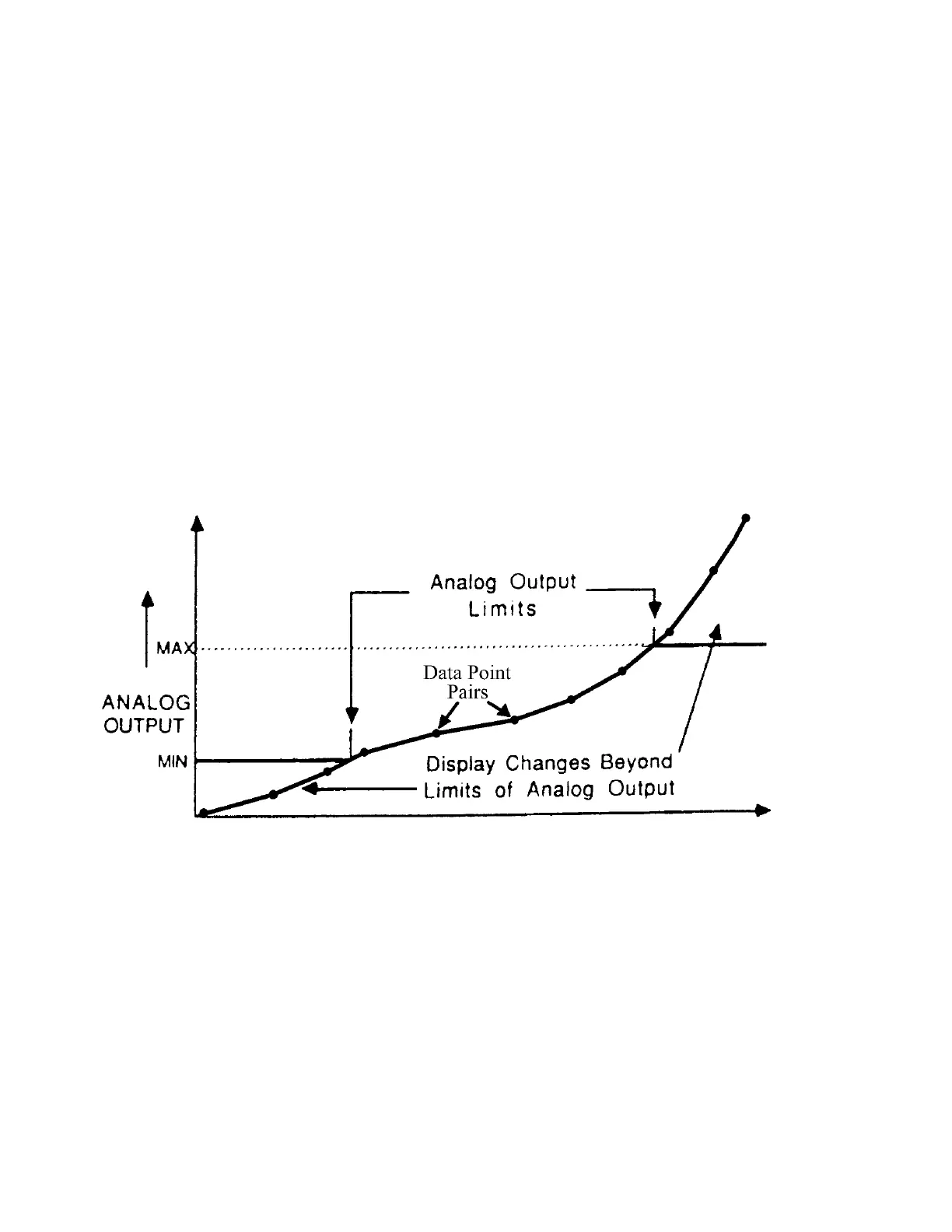
The analog output will span the minimum and maximum limits, just as it would in the
linear scaled mode. The analog output will follow the non-linear, converted scale being
displayed. To select this operating mode, use the OP 2, Func, MODE command to change
the value to “2”.
Figure 2.3 Non-linear Scaled Mode Analog Output