32 of 33
Service Manual UK
Indesit
Company
English
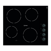
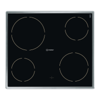
C) Touch Control Printed Circuit Board
1. Remove the hob top (A).
2. Remove the 5 wire plug from the PCB.
3. Disengage the plastic securing lugs and lift clear. See Figs. 7 - 8.
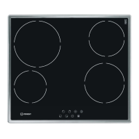
D) Power Board
1. Remove the hob top (A).
2. Unplug the small two wire plug for each element.
3. Remove all the element main wires by releasing the T15 Torx screws.
4. Remove the five T15 Torx screws securing the plastic base to the chassis.
5. Carefully lift the metal chassis up and release the Earth wire.
6. Lift clear complete with the elements and place to one side.
7. Disconnect the wiring, unclip the power board and lift clear. See Figs. 9 - 11.
8. When reassembling, ensure the Earth wire is reconnected to the metal chassis.
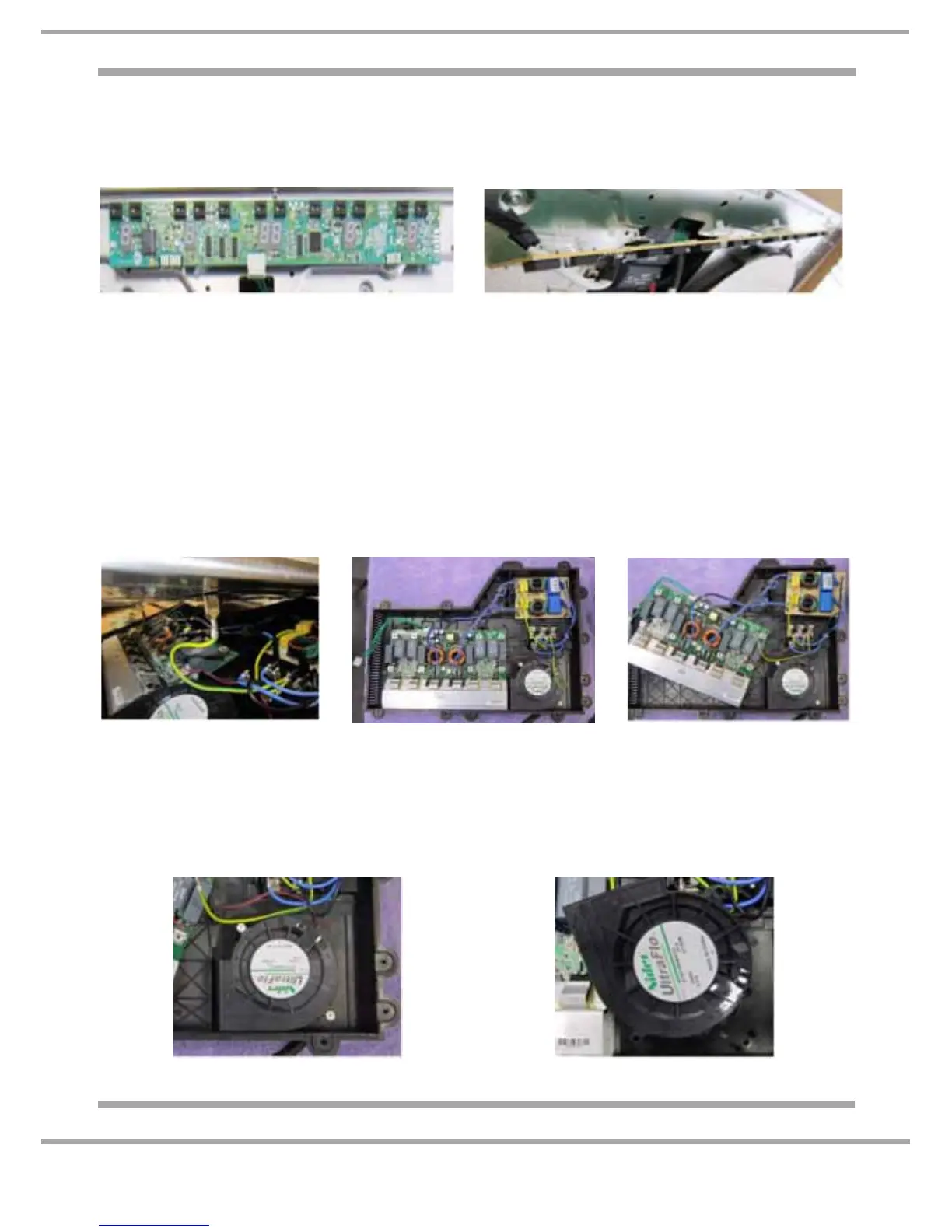
E) Fan
1. Follow power board (D) 1-6.
2. Remove the two T15 Torx screws.
3. Disconnect the wiring and lift clear. See Figs. 12 - 13.
Fig. 7 Fig. 8
Fig. 9
Fig. 12
Fig. 10 Fig. 11
Fig. 13