Do you have a question about the Indesit VIA640C and is the answer not in the manual?
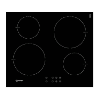
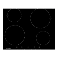
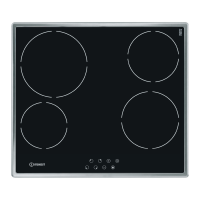
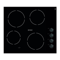
Details of the hob's technical characteristics including dimensions, weight, and power ratings.
Specific safety instructions for handling chip pan fires and general fire safety.
Guidelines for installing the hob into a worktop, including material and oven compatibility.
Requirements for hob positioning and ventilation to prevent overheating.
Instructions for correctly fixing the hob to the supporting surface using screws and hooks.
Emphasizes the critical need for proper earthing for electrical safety.
Details on connecting the hob to the mains supply via a double pole switch.
Explanation of the hob's stand-by mode and power consumption limitations.
Describes various noises produced by induction hobs and their causes.
Procedure for turning the hob on and off.
How to select and adjust power levels for cooking zones.
Steps to switch off individual cooking zones.
How to lock and unlock the control panel to prevent accidental changes.
Procedure for turning the entire hob off.
Functionality of the pan sensor and indicator lights.
How the overheating protection mechanism operates and displays errors.
Explanation of the automatic shutdown feature based on operating time.
Indicates common reasons for the buzzer sounding and its behavior.
Detailed instructions and warnings for cleaning the hob surface and components.
Fault code F01 related to visual board NTC status and check actions.
Fault code F02 for communication module issues and troubleshooting steps.
Fault code F03 for keyboard or communication errors and resolution.
Fault code F04 concerning high temperature of the visual board.
Fault code F05 for NTC sensor issues on induction hotplates.
Fault code F06 related to NTC sensor issues on small induction hotplates.
Fault code F07 for NTC sensor issues on large induction hotplates.
Fault code F08 for NTC sensor issues on small induction hotplates.
Fault code F09 for incomplete setting files or touch control issues.
Fault code F10 related to heat-sink NTC sensor status.
Fault code F11 for heat-sink NTC sensor status on specific modules.
Fault code F12 for high temperature issues related to the fan.
Fault code F13 for high temperature issues related to the fan on specific modules.
Fault code F14 for high temperature issues on the large hob.
Fault code F15 for NTC calibration issues on the power board.
Fault code F16 for NTC calibration issues on the power board.
Fault code F17 for NTC calibration issues on the power board.
Fault code F18 for communication errors between boards.
Fault code F19 for communication errors between boards.
Essential safety precautions before and during dismantling procedures.
Steps to dismantle the hob top and glass.
Procedure for removing and accessing the induction plates.
Steps to remove the touch control printed circuit board.
Instructions for removing the power board and filter assembly.
Procedure for removing and replacing the fan and seal.
Steps to remove the suppressor and cable assembly.
Programming procedure for authorized engineers using specific hardware and software.
Programming procedure for qualified persons using a Smartcard reader.
| Type | Gas Hob |
|---|---|
| Number of Burners/Zones | 4 |
| Width | 60 cm |
| Ignition Type | Automatic |
| Safety Features | Flame Failure Device |
| Gas Type | Natural Gas |
| Dimensions (WxD) | 590 x 510 mm |