TC1784
Analog to Digital Converter (ADC)
User´s Manual 23-33 V1.1, 2011-05
ADC, V1.3
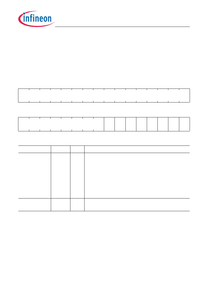
23.2.6.3 Interrupt Activation Register
The interrupt activation register contains bit locations allowing to activate one or more
service request outputs SR[7:0] of the ADC kernel. Writing a 1 to a bit position x activates
the corresponding SRx line. All bit positions read as 0.
INTR
Interrupt Activation Register (204
H
) Reset Value: 0000 0000
H
31 30 29 28 27 26 25 24 23 22 21 20 19 18 17 16
0
r
1514131211109876543210
0
SI
SR7
SI
SR6
SI
SR5
SI
SR4
SI
SR3
SI
SR2
SI
SR1
SI
SR0
r wwwwwwww
Field Bits Type Description
SISRx
(x = 0 - 7)
xwSet Interrupt for SRx Line
Writing a 1 to a bit position sets an interrupt request
at the SRx output of the ADC kernel (the activation is
finished automatically). Writing a 0 has no effect. The
read value is always 0.
0
B
No action
1
B
The service request output SRx of the ADC
kernel becomes activated.
0 [31:8] r Reserved
Read as 0; should be written with 0.
 Loading...