3
ROUTING THE WIRES
All signal and power wires should be routed
through the opening provided at the rear of the
connection panel. On the rear of Basslink T are
two channels extending from the opening — one
horizontal, and one vertical — that may be used for
routing those wires to the vehicle.
Depending on installation requirements, all, or
some, of the wires may be routed straight down
along the vertical channel to the floor and hidden
under the carpeting, and/or across the horizontal
channel toward the side and hidden behind the
vehicle’s trim panels.
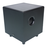
Figure 5. Channels for wiring.
ADDITIONAL MOUNTING FEET
If your particular application inhibits the ability to
secure the lower portion of BassLink T, please use
the supplied mounting feet. They slide into the
channels on the bottom of the unit and snap in
place. This will give you the ability to secure
BassLink T to the floor of your vehicle.
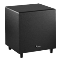
Figure 6. BassLink T installation with optional feet.
MOUNTING BASSLINK T (CONTINUED)
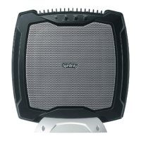
Connect power to BassLink T, as shown in
Figure 7. Also observe these installation tips:
•
Use at least #10 AWG wire for the +BATT
(+12 Vdc) and GND (ground) connections. If
needed, use at least a #20 AWG wire for the
REM (remote) connection.
•
Route all power wires through a grommet in
the vehicle’s firewall. If a factory grommet is
unavailable, install one.
•
Connect a short GND wire from BassLink T
to the nearest bare metal surface. For a
good connection, scrape away paint from
the metal surface and use a screw with a
lock (star) washer.
•
Install a fuse holder with a 25 A fuse within
18" of the battery’s positive (+) terminal (see
Figure 7).
•
The REM connection requires +5 to +12 Vdc
signal to turn on BassLink T. Most head units
with preamp outputs provide this remote
voltage signal. For speaker-level applications,
a remote connection is preferred but not
required, since BassLink T’s Auto Turn-On
feature will sense voltage on the speaker
wires to automatically turn on BassLink T.
IMPORTANT: To enable BassLink T’s Auto
Turn-On feature, set the AUTO TURN-ON
switch to the AUTO position (see Figure 13
on page 7).
Figure 7. Power connections for BassLink T.
POWER CONNECTIONS