1. A
lower
amplifier input impedance will result in a
higher
crossover point at a given switch
position.
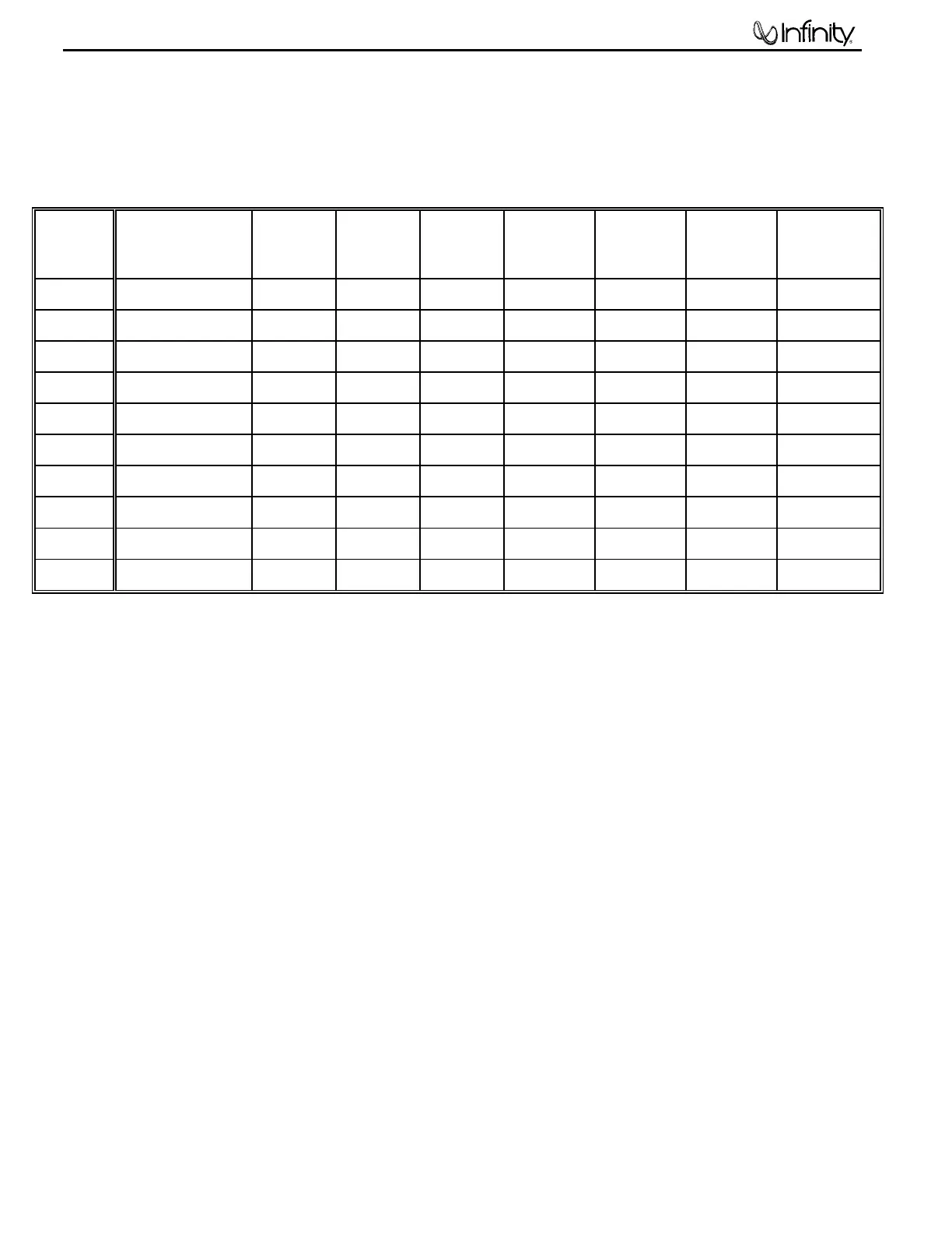
2. As the switch positions progress, (options 1 - 10) they result in a
higher
crossover point.
OPTION
#
INPUT
IMPEDANCE
RANGE (OHMS)
SWITCH
6
SWITCH
5
SWITCH
4
SWITCH
3
SWITCH
2
SWITCH
1
SHUNT
RESISTOR
*
1 8 -12K DOWN DOWN UP DOWN DOWN DOWN -
2 12 -18K UP UP DOWN DOWN DOWN DOWN -
3 16 - 24K UP UP DOWN UP DOWN DOWN -
4 26 - 40K UP UP DOWN UP UP DOWN -
5 40 - 60K UP UP UP UP UP DOWN -
6 70 - 80K UP UP UP UP UP DOWN 200K
7 80 - 120K UP UP DOWN UP UP UP -
8 120 - 200K UP UP UP UP UP DOWN 68K
9 200 - 500K UP UP UP UP UP DOWN 56K
10 500K - 1MEG UP UP UP UP UP DOWN 51K
* The "shunt resistor" mentioned in the latter options is a ¼ watt resistor soldered across an RCA male plug (2
required). These are plugged into the adjacent high pass output jacks you will be using (internally in parallel).
The purpose is to present a lower input impedance to the ECU filter for more optional settings. If you are
unable to assemble these or have no access to the correct parts call Infinity Systems.
EXAMPLE #1:
We have an amplifier with an impedance of 20k, but we want a higher crossover point than 140
Hz.
SOLUTION:
Try switch options 4 or 5.
EXAMPLE #2:
We have an amplifier with an impedance of 75k, but we want a lower crossover point than 140
Hz.
SOLUTION:
Try switch options 1,2,3, or 4.
IV KNOB RECOMMENDATIONS:
Again, if using the high pass filter
only
on the ECU: all knob positions are irrelevant (including power) as the filter
section is a separate, passive section.
If you are using a powered subwoofer of some type other than the Infinity subwoofer designed for this system, we
recommend using either one set of controls or the other; It would be redundant to manipulate both sets of controls. If
you are going to use the controls on your subwoofer, set the "Crossover" and "Level" knob to the ECU on full CW
(clockwise); set the "Phase" knob on "0" (full CCW); set the "22/35" Hz switch on 22 Hz. Then use the frequency and
gain controls on your subwoofer
only
. If you are going to use the ECU controls only, set the "Crossover" knob on the
subwoofer at full CW and start with the "Level" control at 12 O'clock (half-way). If more gain is needed (after turning
the ECU gain up during testing) then the level pot can be turned up further. Then use the frequency and gain controls
on your ECU
only
.
If you have a powered subwoofer of some other brand that does not have a gain or frequency control, use the
controls on the ECU with discretion.
Modulus