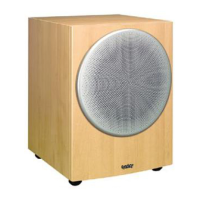
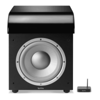
MODULUS AMPLIFIER ADJUSTMENT
(Performed with the Amplifier out of the cabinet)
Attach the amplifier to the power supply (using both molex connectors) and to the
ECU (with the grey control cable) just like it would be powered if it were fully assembled. The following
describes a method to drive the amplifier at a certain input voltage and frequency from the ECU, and to
take measurements at two different frequency points (low and high) at the output of the amplifier. It also
describes the approximate correct pot positions of VR1, VR2 & VR3.
Place VR1 = approx. middle position
Connect and power up the amp (to power supply and ECU). Do not attach any load to the amp output
(woofer) cables or to the three-wire feedback cable during this test. Connect a function/signal
generator the RCA input jacks of the ECU, both channels (use a Y-cable if necessary).
ECU CONTROLS:
LEVEL - FULL CW
PHASE - "0"
CROSSOVER - FULL CW
22/35 Hz - 22 Hz Position
TEST #l: 10mV, 20 Hz input to the ECU should yield: 1.95 volts at output (red wires)
TEST #2: 10mV, 300 Hz input to the ECU should yield: 445 mV at output (red wires)
VR2 - 2/3 to 3/4 CW Note: Adjusting VR2 only changes the upper frequency range
VR3 - Nearly or full CW Note: Adjusting VR3 changes output all frequencies
The variable resistor (pot) on the small board on the woofer is normally full Clockwise.
Modulus