SYSTEM AURAL SWEEP TEST
Equipment needed:
• Function/signal generator/sweep generator
• High Gain Integrated Amplifier
• Multimeter
• Speaker cables
General Unit Function (UUT = Unit Under Test)
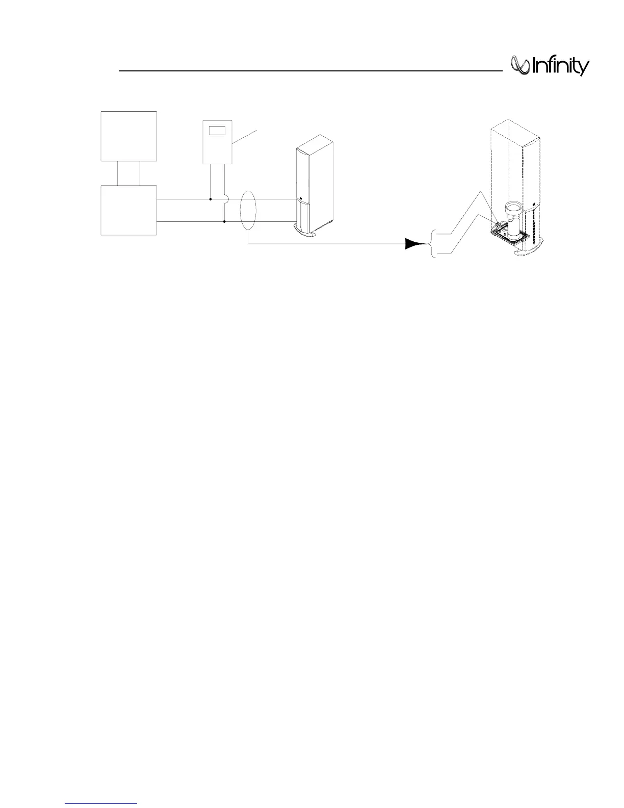
1. From the signal generator, connect a mono cable to the Integrated amplifier; with speaker cables connect the amplifier’s
output to the UUT Speaker binding posts.
2. On the UUT, turn the BASS (level) control full counterclockwise (1).
3. Turn on generator, adjust so that the output at the Integrated amplifier is 2.0V, 40 Hz.
4. Plug in UUT; LED should be Red. Turn BASS (level) control full clockwise (9).
5. LED should now be Green and immediate bass response should be heard (and observed if the grille is removed).
Sweep Function
6. Follow steps 1-5 above.
7. Sweep generator from 20Hz to 300Hz. Listen to the cabinet and drivers for any rattles, clicks, buzzes or any other noises. If
any unusual noises are heard, remove woofers and test.
Driver Function
8. Remove woofer from cabinet; detach + and - wire clips.
9. Check DC resistance of woofer; it should be:
(120v) - 14.2 Ohms ±10%
(230v) - 40.0 Ohms ±10%
10. Connect a pair of speaker cables to driver terminals. Cables should be connected to a high-gain integrated
amplifier fed by a signal generator. Turn on generator and adjust so that speaker level output is 20.0V. *
11. Sweep generator from 20Hz to 1kHz. Listen to driver for any rubbing, buzzing, or other unusual noises.
*
Only the 120v version will be driven to near maximum excursion at this voltage; because of the unusually high DCR of the voice coil,
driving the 230v version at twice this voltage is not practical with simple test equipment and 20v should suffice for test purposes.
Amplifier bias adjustment
1) Power up loudspeaker and drive at low levels for 3 minutes for warm-up.
2) Remove amplifier assembly (disassembly procedure in bulletin INF9704 Page 15).
3) Power up on the bench; attach DMM (on low DC voltage range) across TP1 and TP2 on schematic – R77 - (120v) .22 Ω 5W
fuse resistor. (230v) .47 Ω 5W fuse resistor. Mini-grabbers can be used on the resistor leads without PCB removal.
4) Adjust POT2 (bias pot on PCB) to read 5.9 mV for both 120v and 230v units.
 Loading...