Introduction
8 Infoblox Installation Guide
Ethernet Port LEDs
To see the link activity and connection speed of an Ethernet port, you can look at its Activity and Link LEDs. Figure 2
shows the status the LEDs convey through their color and illumination (steady glow or blinking).
Figure 2 LEDs
Connector Pin Assignments
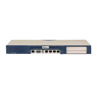
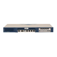
An Infoblox appliance has three types of ports on its front panel:
• USB port (reserved for future use)
• Male DB-9 console port
• Three (3) RJ-45 10Base-T/100Base-T/1000Base-T auto-sensing gigabit Ethernet ports (HA interface disabled)
— Available 10-gigabit Ethernet SFP+ configuration or 1-gigabit Ethernet SFP configuration (see 10 Gigabit
Ethernet Support section)
The DB-9 and RJ-45 connector pin assignments are described in Figure 3. The DB-9 pin assignments follow the
EIA232 standard. To make a serial connection from your management system to the console port, use the RJ-45
rollover cable and two female RJ-45-to-female DB-9 adapters that ship with the appliance. RJ-45 pin assignments
follow IEEE 802.3 specifications. All Infoblox Ethernet ports are auto-sensing and automatically adjust to standard
straight-through and cross-over ethernet cables.
Label Color Port Status
Activity Blinking Green Link is Up and Active (SFP+ only)
Steady Yellow
Link is up but inactive
Blinking Yellow
Link is up and active
Dark
Link is down
Link Steady Blue 10000 Mbps (SFP+ only)
Steady Amber 1000 Mbps
Steady Green 100 Mbps
Dark 10 Mbps
 Loading...