9
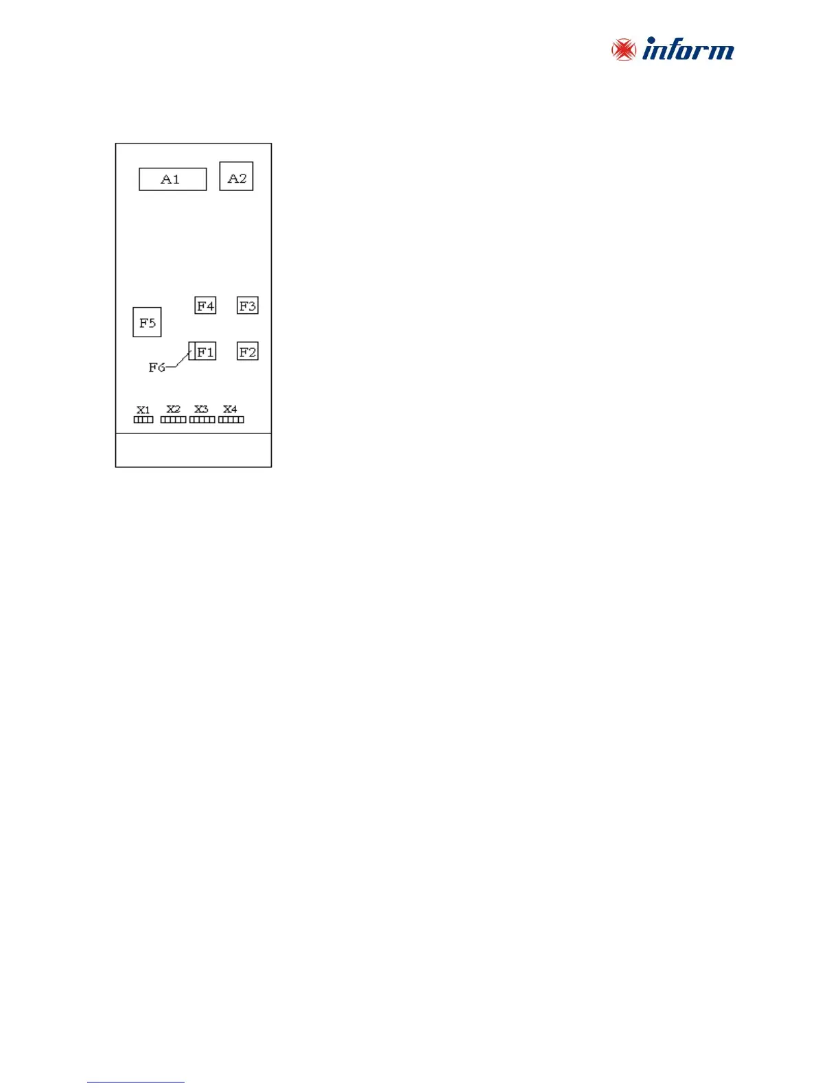
Layout of the connection terminals and boards are shown below:
A1: Communication interface board
A2: Parallel connection board (optional)
F1: Input circuit breaker
F2: Output circuit breaker
F3: Manual by-pass circuit breaker
F4: By-pass circuit breaker (optional)
F5: Battery circuit breaker
F6: Inrush fuse
X1: Battery terminals
X2: Input mains terminals
X3: Separate by-pass mains terminals (optional)
X4: Output terminals